Eerste idee: ongeveer 2000
Wisseldrukmatras geprobeerd: 2009 ... 2011
Eerste versie van mijn zelfgemaakte matras met beweging: 2012
Al vele jaren liep ik met het idee om mijn wervelkolom zachtjes in beweging
te houden, terwijl ik slaap.
Omdat ik alleen om mijn rug kan liggen vanwege mijn nekproblemen, lig ik te stil en te vast
tijdens het slapen. Ik wilde dus een actief bewegend matras.
Ik had dit met anderen besproken en zelfs een advertentie in een lokale krant gezet
om aan anderen hulp te vragen.
Dat leverde uiteindelijk niets op.
Ik probeerde een wisseldrukmatras
om mijn wervelkolom in beweging te houden als ik slaap.
Dat lukte niet, omdat het teveel beweging voor mijn nek was.
Er zijn ook apparaten te koop die masseren door een vibrerende motor, maar ik wil
mijn wervelkolom in beweging houden met kleine en langzame bewegingen.
Daarom besloot ik om zelf iets te gaan maken.
Dat kostte me echter zoveel moeite, dat ik me vaak afvroeg of het wel de moeite waard was.
Maar na een week met een eerste test bleek al dat het een duidelijk positief effect had.
Een mechanische constructie zou ingewikkeld worden.
Met luchtcompartimenten en met luchtdruk is eenvoudiger en dat is ook veilig.
Tijdens het maken wist ik nog niet hoe het zou gaan worden.
Ik dacht dat ik ergens tussen de 2 tot 40 luchtcompartimenten nodig zou hebben,
die ik allemaal afzonderlijk zou willen kunnen programmeren wanneer ze oppompen
en wanneer ze leeg lopen.
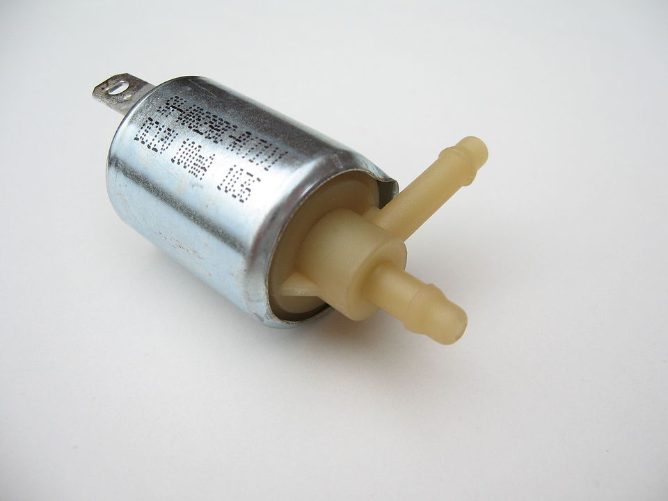
Ik probeerde een paar luchtpompen en een paar kleppen (solenoid valves).
Voor mijn testen gebruikte ik een doorstromingsmeter (flow meter), en een druk meter.
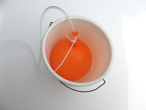
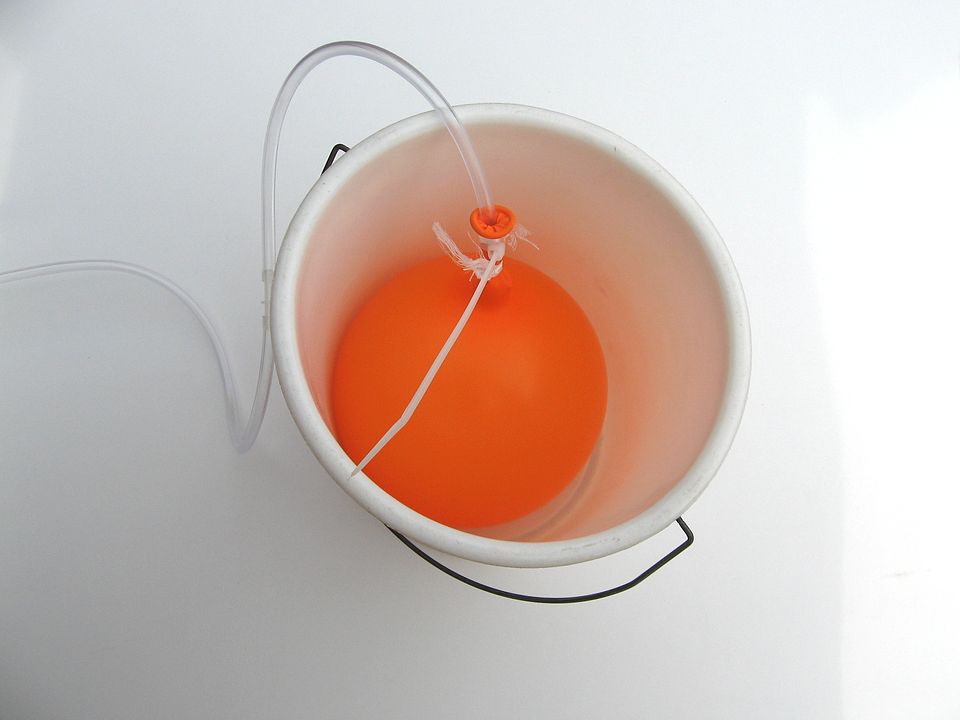
Doorstromingsmeter (flow meter)
Om de hoeveelheid lucht die de pompen konden leveren te meten,
had ik een doorstromingsmeter voor lucht nodig (air flow meter).
Ik gebruikte daarvoor de "ballon-in-de-emmer" flow meter.
Ik plaats een lege ballon in een emmer, en laat de lucht in de ballon lopen.
Zodra de ballon klem zit, stop ik de tijd. De tijd die nodig is om de ballon op te pompen,
is om te rekenen naar de hoeveelheid liters per minuut.
De tegendruk die de ballon geeft was maar weinig (40 mbar).
Mijn metingen met de "ballon-in-de-emmer" methode bleken niet erg betrouwbaar.
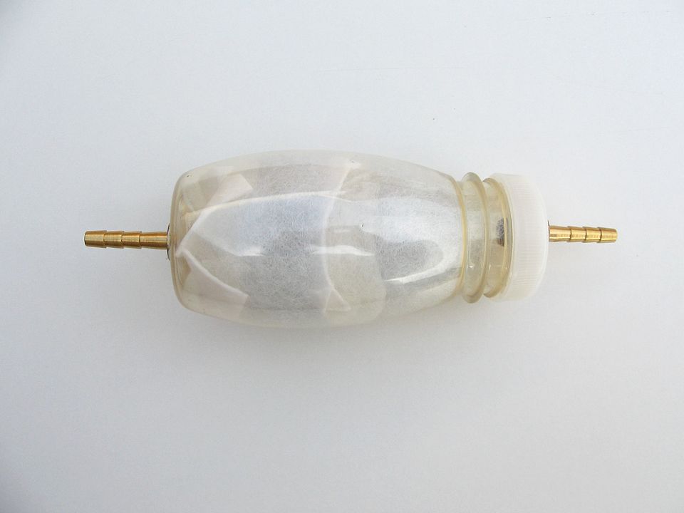
Later gebruikte ik een luchtcompartiment van niet-elastisch materiaal (pvc).
Ik dompelde dat eerst onder in water, om te inhoud te meten. Het bleek 2.4 liter te zijn.
Vervolgens keek ik hoelang het duurde voordat hij vol was. Mijn metingen waren
daarmee een stuk beter.
Er bestaan ook doorstromingsmeters voor lucht, die in auto's gebruikt worden.
Ze zijn nogal duur, maar ze zijn ook tweedehands te koop.
Ik heb er geen gekocht, zo belangrijk was het meten van de luchtstroom nu ook weer niet.
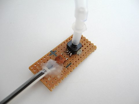
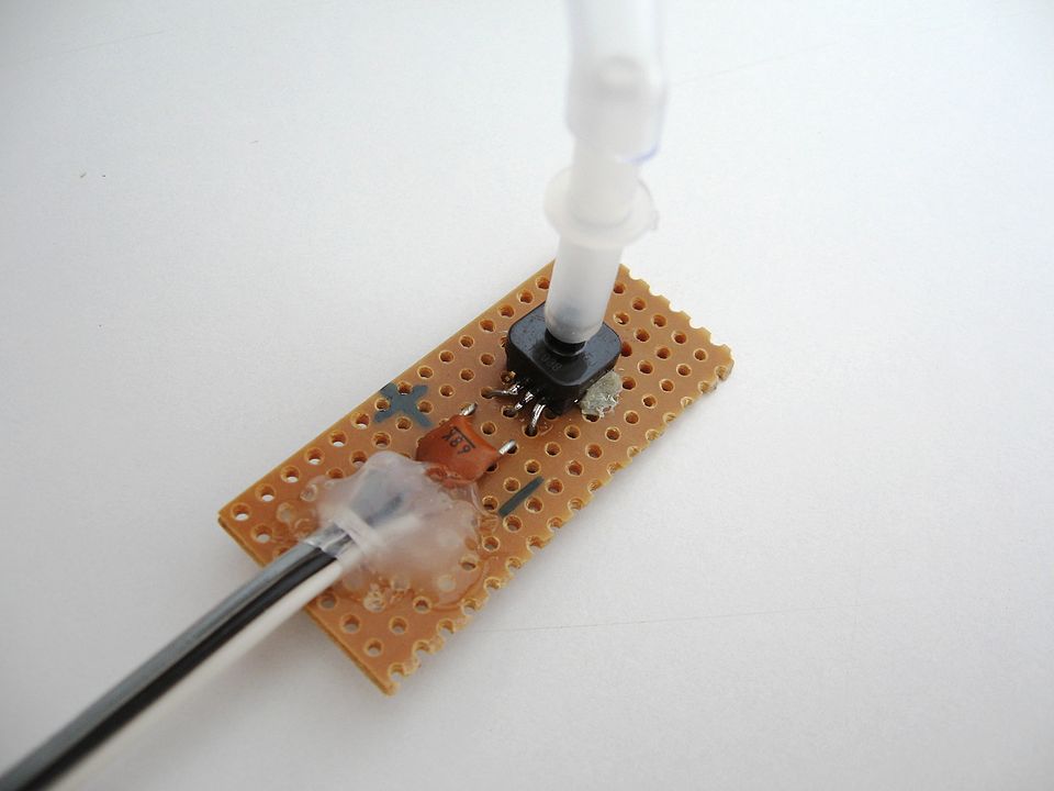
Druk meter
Om de druk te meten had ik een drukmeter nodig, die zowel positieve druk als negatieve
druk (vacuüm) kon meten. Ik kwam zo op een MPXH6400A sensor.
Deze werkt op 5V en meet de absolute druk. De sensor is dus ook een barometer.
De sensor geeft een analoog signaal af. Het bereik van de sensor is -0,8 tot 3 bar.
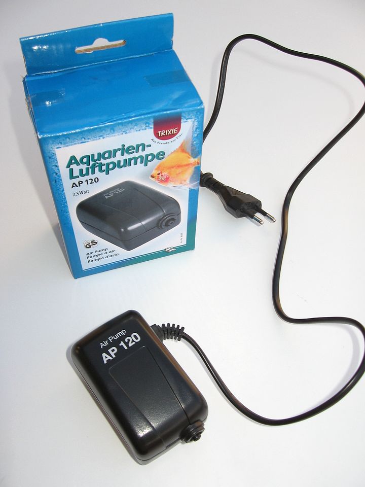
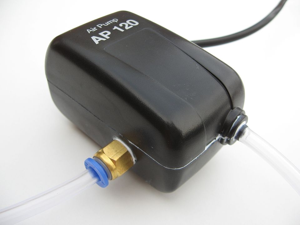
Na wat proberen kwam ik er achter dat sommige aquariumpompen bijna voldoende druk geven.
Ik heb goede aquariumpomp gekozen, die zijn mechanisch en elektrisch van veel betere
kwaliteit dan de goedkope.
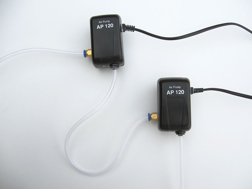
Om meer druk te krijgen, gebruik ik twee aquariumpompen om zo de druk te verdubbelen.
Goede aquariumpompen zijn stil en gaan jaren mee, dat is precies wat ik nodig had.
Sommige aquariumpompen kunnen 0.2 bar druk leveren.
Door er twee achter elkaar te zetten, had ik 0.4 bar druk. Dat bleek ruim voldoende te zijn.
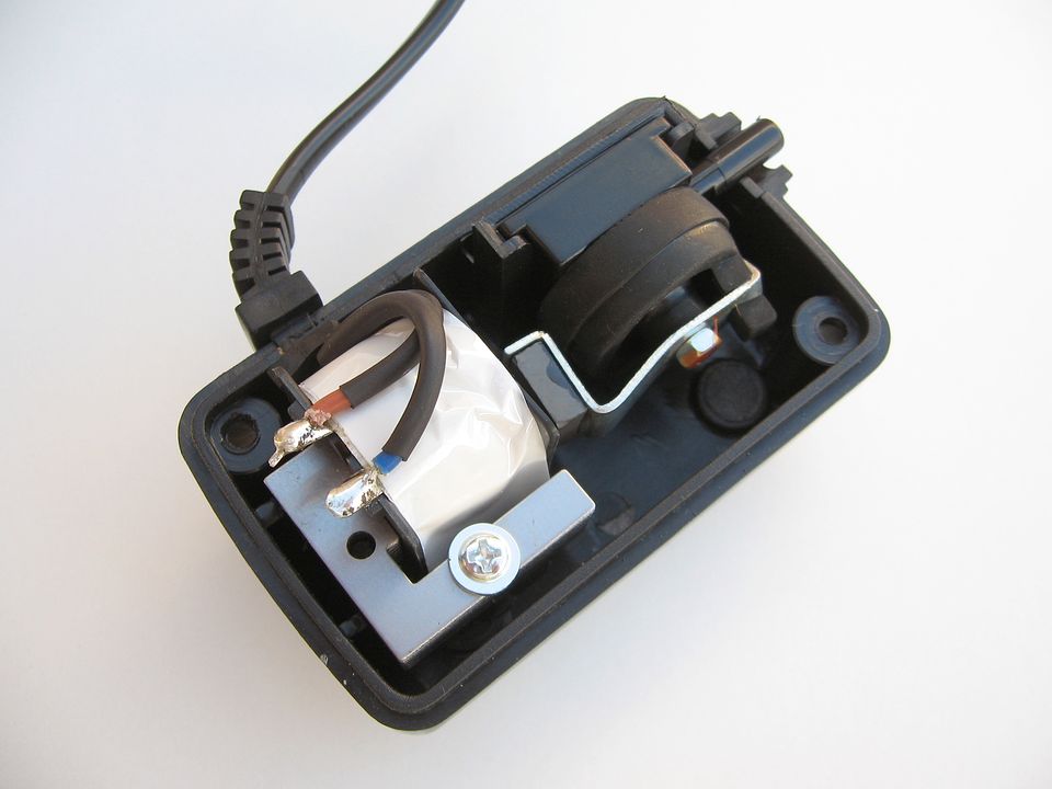
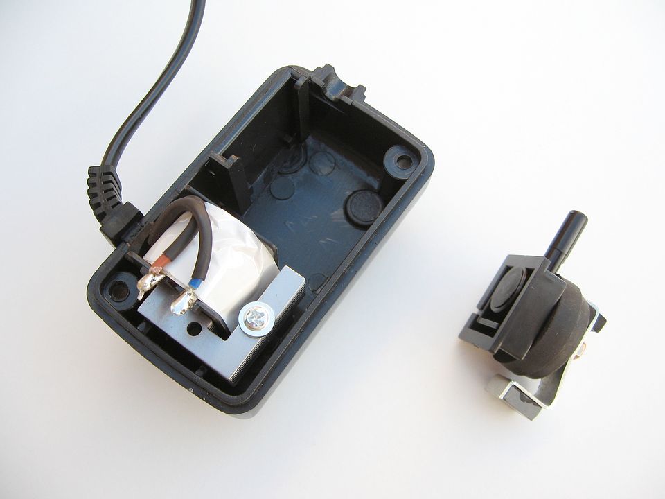
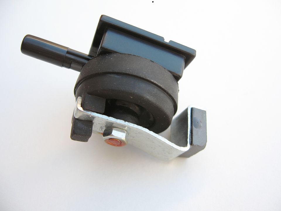
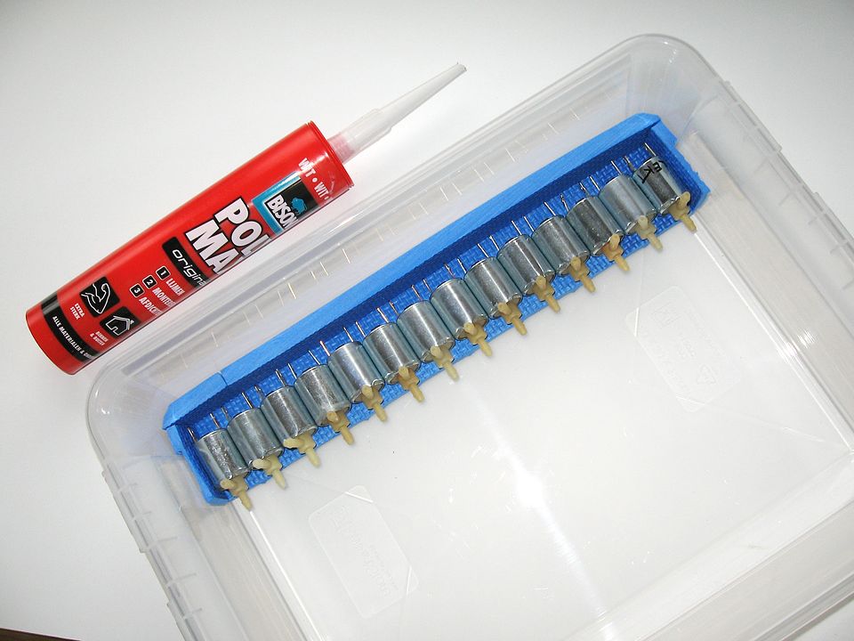
Om twee pompen achter elkaar te zetten, moest ik een luchtinlaat maken in de pompen.
De luchtinlaat maakte ik in de behuizing, en de behuizing maakte ik dicht met kit.
Omdat ik nu een luchtinlaat had gemaakt, had ik ook een luchtfilter nodig om
de pompen schoon te houden.
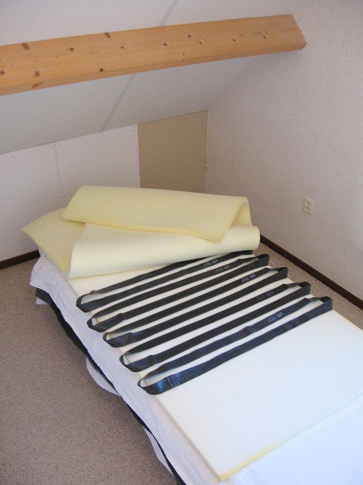
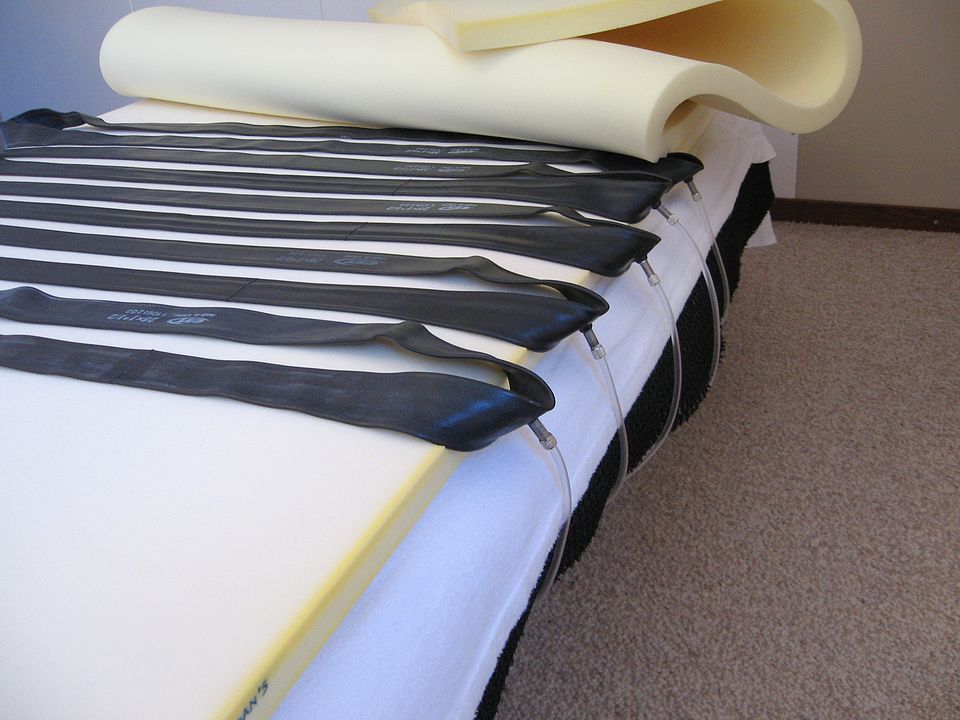
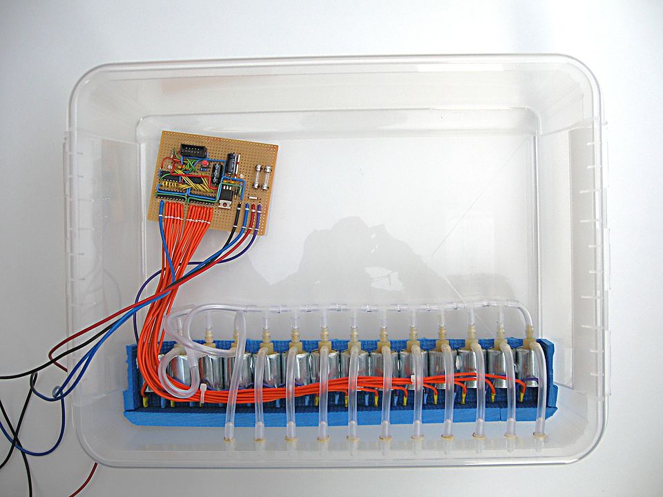
Omdat ik mijn matras met lagen gebruikte,
kon ik de luchtcompartimenten tussen de lagen van mijn matras leggen.
Als luchtcompartimenten gebruikte ik binnenbanden van een fiets.
Het rubber van de fietsbanden is eigenlijk te dik, en dat beïnvloed het matras.
Iets beters heb ik echter nog niet kunnen vinden.
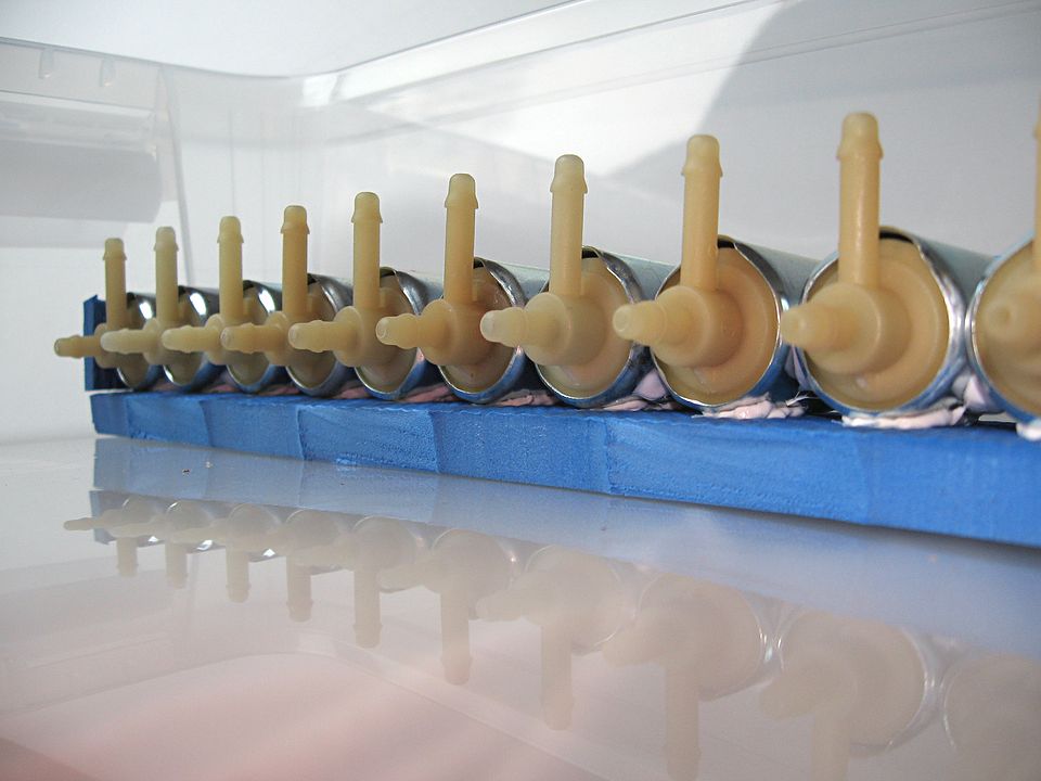
Ik kon tweedehands kleppen (solenoid valves) kopen, die ideaal waren voor de lage druk en lage
doorstroming die ik gebruik.
Er pasten 14 kleppen in de doos die ik had gekocht voor de besturing.
Op de doos stond onderop "PP-05". Dat betekent dat het gemaakt is van polypropeen.
Als ik daar gaten in zou boren, dan zou het scheuren en breken.
Ik maakte daarom een boortje heet boven een vlam en maakte daarmee
de gaten voor aansluitingen van de slangen.
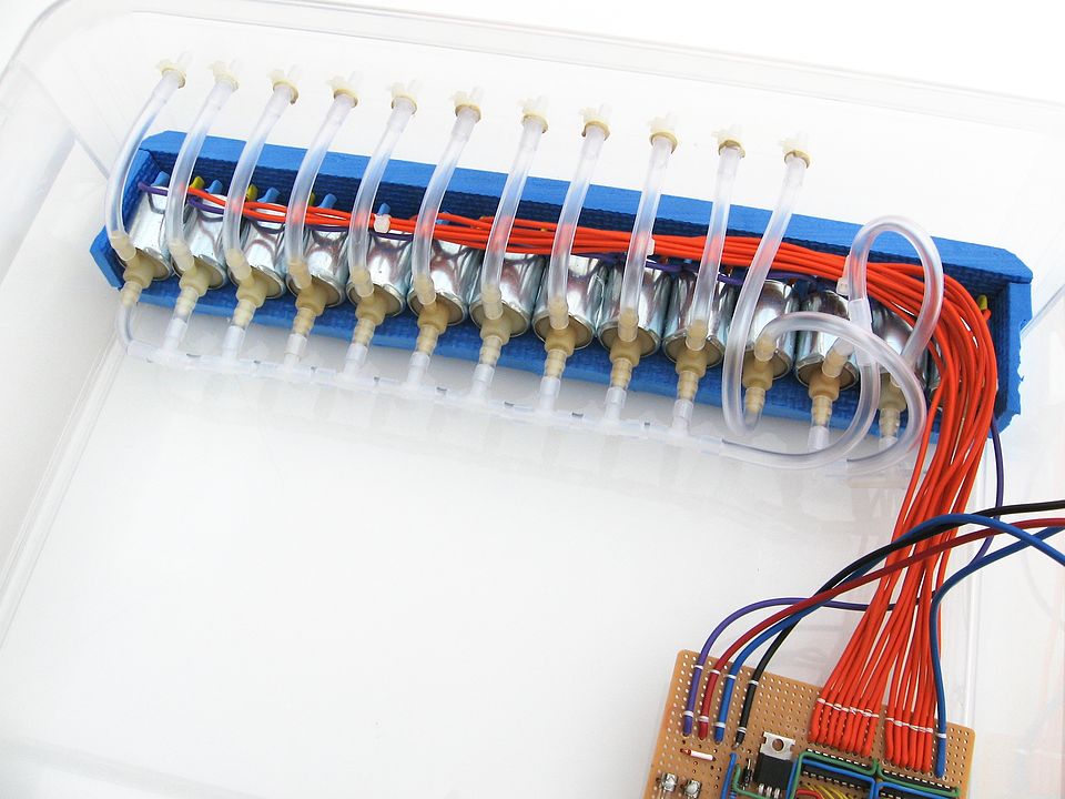
Om alle kleppen tegelijkertijd te kunnen laten oppompen of laten leeglopen,
zou ik twee hoofdlijnen nodig hebben: een lijn voor positieve druk,
en een lijn voor negatieve druk (vacuüm).
Maar dan zou elk luchtcompartiment twee kleppen nodig hebben, om te kunnen
kiezen tussen de beide hoofdlijnen. Dat maakt alles ingewikkelder.
Ik wil in ieder geval de pomp gebruiken om de luchtcompartimenten helemaal
leeg te maken, zodat er geen lucht in het luchtcompartiment achterblijft.
Daarom koos ik er voor om slechts één klep per luchtcompartiment te
gebruiken, die met hun allen op één hoofdlijn aangesloten zijn.
Vervolgens had ik wel 4 kleppen nodig om de pomp te gebruiken
voor het opblazen en leeg maken van de luchtcompartimenten.
Het zou misschien met minder kleppen kunnen, maar het lijkt mij beter
om geen omgekeerde luchtstroom door het luchtfilter te laten lopen.
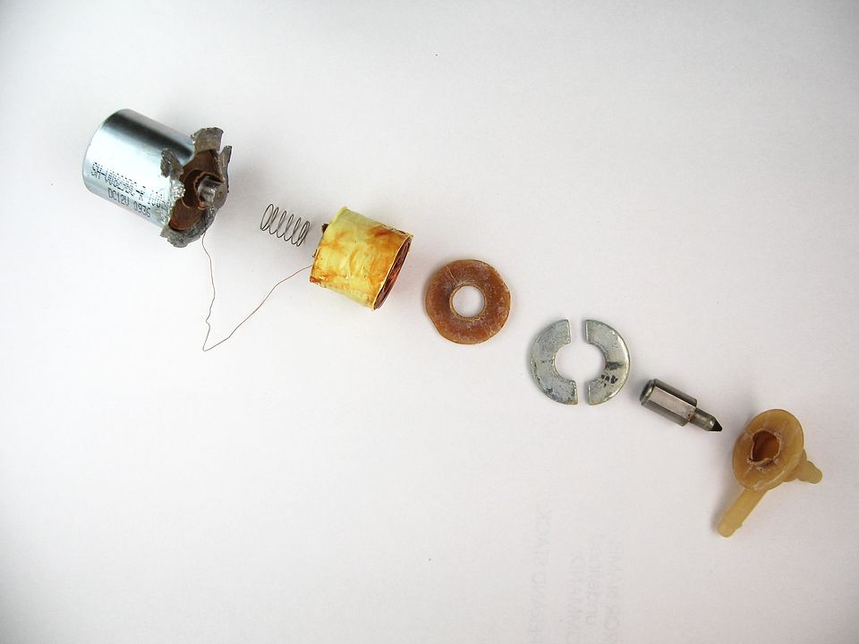
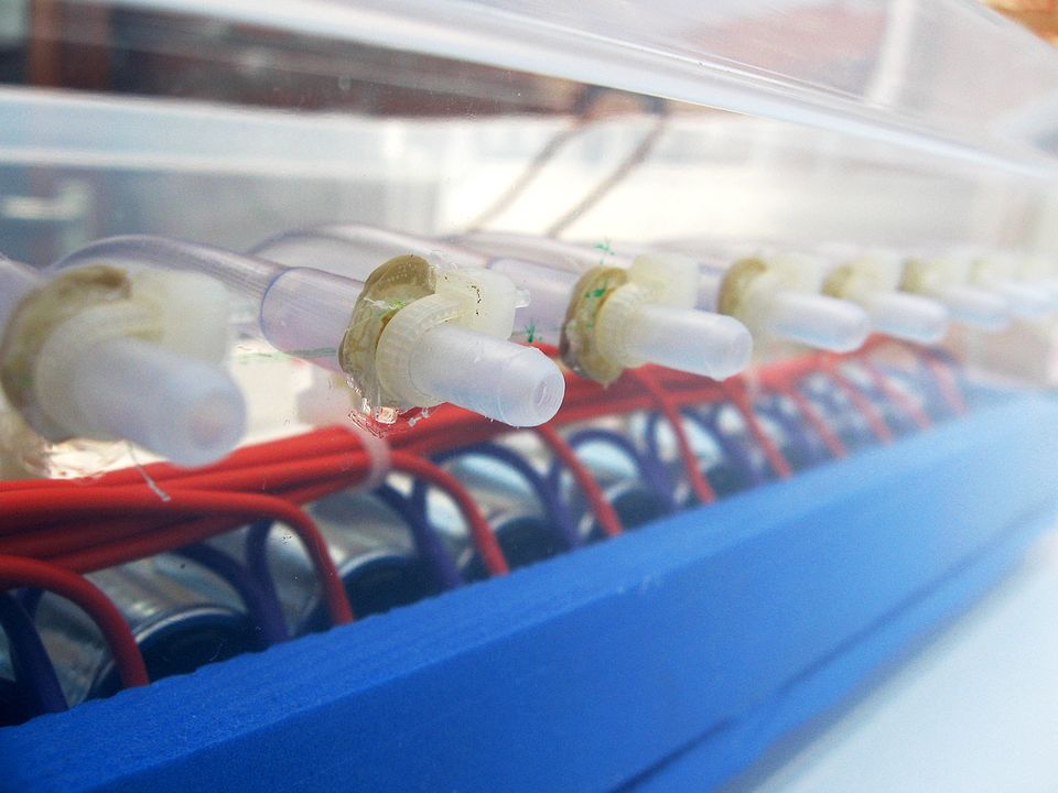
De kleppen zijn geschikt voor een luchtstroom in één bepaalde richting.
Op de ingang kan een klep meer druk weerstaan, en lekken dan het minste.
Bij het aansluiten van de kleppen heb ik niet gekeken naar de richting van de luchtstroom,
maar meer naar welke kant van de klep het beste druk kan weerstaan.
Dit is hoe de kleppen zijn aangesloten (klik op het plaatje voor een grotere versie):
Het plus-teken bij de kleppen geeft aan welke kant de druk kan weerstaan.
Om alles te besturen had ik iets nodig dat ik kon programmeren.
De meest geschikte microcontroller hiervoor is een AVR microcontroller.
Op internet zijn daar veel voorbeelden van te vinden, en veel mensen zijn bereid te helpen.
De Arduino is bedoeld voor dit soort dingen, maar zowel de hardware
als de software was te ingewikkeld voor me.
Toen ik dit matras met beweging had afgerond, begreep ik
intussen wel de Arduino. Die kennis kon ik
gebruiken voor mijn
voetschakelaar met Arduino Leonardo.
De Raspberry Pi was toen nog niet te koop.
Het was mijn werk om programma's te schrijven voor in apparaten.
Door mijn nekproblemen kostte het mij echter veel meer moeite
om zoiets te doen. Wat ik vroeger in een dag deed, kostte mij
nu meer dan een week (en alleen als ik er fit genoeg voor was).
Daarom begon ik met een ATtiny13 microprocessor.
Uiteindelijk lukte het me, om daarmee een ledje te laten knipperen.
Vanaf dat punt kon ik verder gaan.
De besturing wilde ik zo eenvoudig mogelijk te maken.
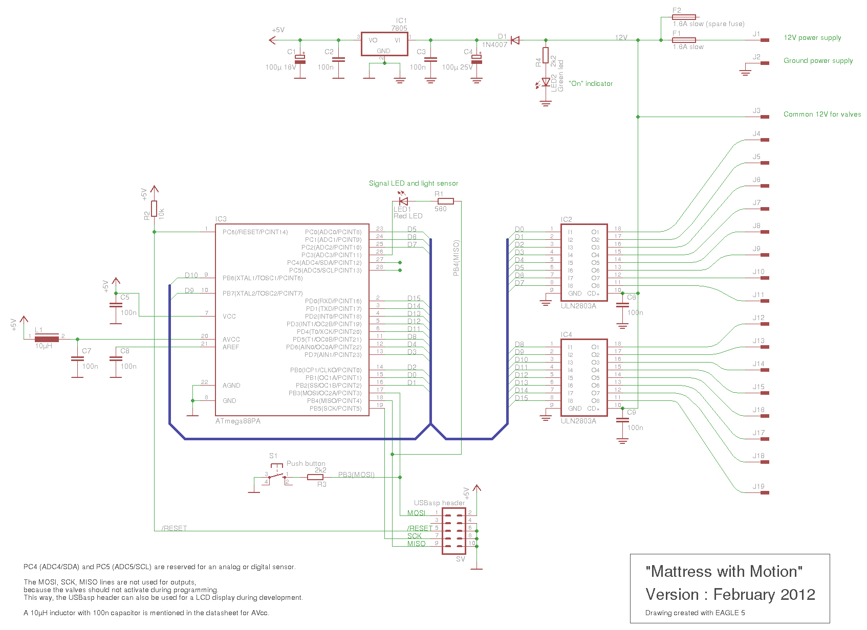
Ik kwam op het volgende ontwerp (klik op het plaatje voor een grotere versie):
Ik koos de volgende onderdelen:
• ATmega88
De ATmega88 is a nieuwe versie van de ATmega8.
Hij heeft voldoende pinnen om mijn 14 kleppen te bedienen.
De 8kbyte geheugen is volgens mij ruim voldoende.
Ik gebruikte een ATmega88PA, die heeft een temperatuur-sensor ingebouwd.
• ULN2803A
Om de kleppen aan te sturen, zou ik losse transistors kunnen gebruiken (bijvoorbeeld BC639)
of "logic level" MOSFETs.
De ULN2803A maakt het echter een stuk eenvoudiger.
De kleppen zijn 100mA, en dat is ruim binnen de specificaties van de ULN2803A.
Er zijn ook geen extra onderdelen nodig om er voor te zorgen dat de kleppen uit blijven
tijdens het aanzetten.
• 7805
De spanningsregelaar voor de 5V zit er op zonder koelvlak,
want er wordt maar weinig stroom gebruikt.
• Signaal LED en licht-sensor
Een LED kan ook als licht-sensor gebruikt worden. Daarom zit de LED (met weerstand) tussen twee pinnen
van de ATmega88.
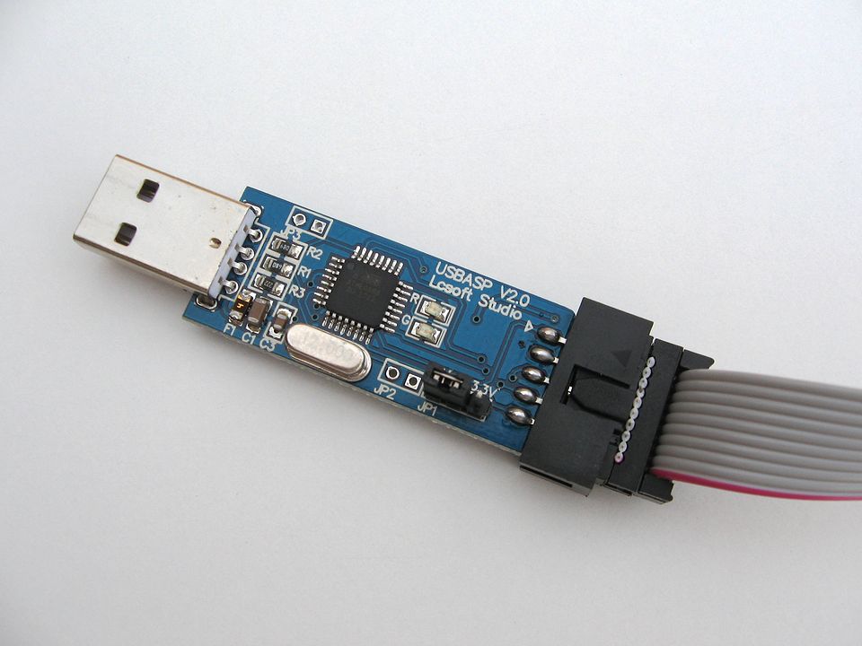
• USBasp
Om te programmeren gebruikte ik de USBasp verbinding.
Een USBasp programmeer-printje kost maar 3 euro.
Zoals in het schema te zien is, zijn er twee soorten nul-lijnen (ground).
Omdat ik de mogelijkheid open wil houden om een analoge sensor
te gebruiken, wil ik niet dat de stroom door de kleppen storing op het analoge gedeelte geeft.
Daarom is zijn de nul-lijnen gescheiden. Bij de 7805 zijn ze aan
elkaar gemaakt.
Dit is zo'n USBasp programmeer-printje:
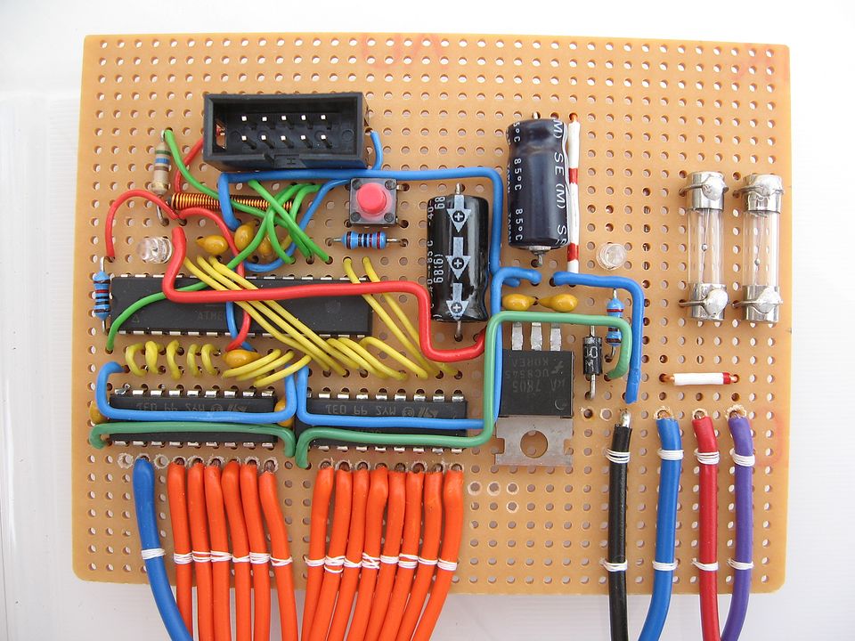
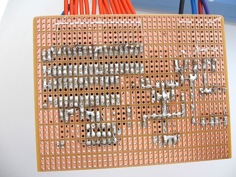
Het lukte me niet om een printplaatje te ontwerpen met een programma.
Daarom heb ik zelf alles met draden gesoldeerd.
Het maken van het printje heb ik verdeeld over een paar weken.
Als ik later meer luchtcompartimenten zou willen hebben, dan is
het nodig om een printplaatje te laten maken.
Hieronder staat de broncode ("mattress.c"):
// ------------------------------------------------
//
//  "Mattress with Motion"
//
//  File    : mattress.c
//  Version : February 2012
//
//  Using the ATmega88PA with ULN2803A drivers.
//  A led is connected between two pins,
//  to be able to use it also as a light sensor.
//  A switch is in the hardware, but not used yet.
//
//  With avr-gcc 4.3.5 in Linux Mint 11 and avrdude 5.10.
//

// The ATmega88PA runs default at 1MHz,
// but can be set to 8MHz with a fuse.
#define F_CPU 1000000UL

#include <avr/io.h>
#include <stdbool.h>
#include <stdlib.h>
#include <util/delay.h>
#include <avr/pgmspace.h>


// To set or clear a bit in a register, I use my own macro's.
#define BIT_SET(port,bit) port |= _BV(bit)
#define BIT_CLEAR(port,bit) port &= ~_BV(bit)
#define BIT_TEST(port,bit) (port & _BV(bit))
#define BIT_INVERT(port,bit) port ^= _BV(bit)

#define TRUE true
#define FALSE false


// Hardware specific definitions
#define SWITCH PB3
#define LED PB4
#define LED_GROUND PC3

// There are 14 valves.
// One output is used to switch the pump on and off.
// So one output is not used and is a spare.
// The wires of the valves are soldered without checking the output number.
// How the valves and air pockets are connected to the outputs is solved by software.

// The next definitions define all the valves and the pump.
// The order is not hardware related.
// The order is only for an index of the valve[][2] array.
enum output_names
{
  VALVE_1 = 0,
  VALVE_2,
  VALVE_3,
  VALVE_4,
  VALVE_5,
  VALVE_6,
  VALVE_7,
  VALVE_8,
  VALVE_9,
  VALVE_10,
  VALVE_OUTLET,
  VALVE_HIGH,
  VALVE_INLET,
  VALVE_LOW,
  PUMP,
  SPARE,
};


// The next definitions define how the air pockets are connected the valves.
// Most of the time, the first pocket is connected to the first valve, and so on.
enum air_pockets
{
  POCKET_1 = VALVE_1,
  POCKET_2 = VALVE_2,
  POCKET_3 = VALVE_3,
  POCKET_4 = VALVE_4,
  POCKET_5 = VALVE_5,
  POCKET_6 = VALVE_6,
  POCKET_7 = VALVE_7,
  POCKET_8 = VALVE_8,
  POCKET_9 = VALVE_9,
  POCKET_10 = VALVE_10,
};


// PORTB can not be used in a constant, because PORTB is a define with calculation.
// So define it with normal values to indicate the port.
enum port_defines
{
  _PORT_A,
  _PORT_B,
  _PORT_C,
  _PORT_D,
};


// Connections of valves.
// The next constant array is located in program code with 'PROGMEM'.
// It translates the definitions for the valves to the hardware connections.
// Both the order and the values should match the hardware.
const unsigned char valve[][2] PROGMEM =
{
  {_PORT_B, PB0},     //  VALVE_1
  {_PORT_B, PB1},     //  VALVE_2
  {_PORT_B, PB2},     //  VALVE_3
  {_PORT_B, PB6},     //  VALVE_4
  {_PORT_B, PB7},     //  VALVE_5
  {_PORT_C, PC0},     //  VALVE_6
  {_PORT_C, PC1},     //  VALVE_7
  {_PORT_C, PC2},     //  VALVE_8
  {_PORT_D, PD0},     //  VALVE_9
  {_PORT_D, PD1},     //  VALVE_10
  {_PORT_D, PD2},     //  VALVE_OUTLET
  {_PORT_D, PD3},     //  VALVE_HIGH
  {_PORT_D, PD4},     //  VALVE_INLET
  {_PORT_D, PD5},     //  VALVE_LOW
  {_PORT_D, PD6},     //  PUMP
  {_PORT_D, PD7},     //  SPARE
};


// defines for valves and pump.
#define OPEN true
#define CLOSE false
#define ON true
#define OFF false


// ###########################################################
// Delay functions
//
// The library functions _delay_ms and _delay_us
// can only delay for about 20 ... 200.
// The actual maximum depends on the frequency of the chip.
// So a workaround should always be added.
// The slight overhead adds some extra delay.

void delay_ms (uint16_t milliseconds)
{
  while ( milliseconds )
  {
    _delay_ms (1);
    milliseconds--;
  }
}

void delay_s (uint16_t seconds)
{
  while (seconds)
  {
    delay_ms(1000);
    seconds--;
  }
}


// ###########################################################
// Function Valve
//
// This function translates the requested valve to the hardware output.
// A valve is closed (or off) if not activated.
// Turning it 'ON' or 'OPEN' activates the output and activates the valve.
// This function can be used with either VALVE_1, or PUMP, and also with POCKET_1, etc.
// The second parameter can be TRUE, FALSE, ON, OFF, OPEN, CLOSE.

void Valve (uint8_t byteValve, uint8_t byteOpen)
{
  uint8_t portdef, pin;
  volatile uint8_t *pPort=NULL;

  portdef = pgm_read_byte (&valve[byteValve][0]);
  pin     = pgm_read_byte (&valve[byteValve][1]);

  // Translate the definition for the port to the actual io-port.
  // Since 'PORTB' is the actual port in the io-register area,
  // using a pointer seems to be the best way to do this.
  switch (portdef)
  {
  case _PORT_B:
    pPort = &PORTB;
    break;
  case _PORT_C:
    pPort = &PORTC;
    break;
  case _PORT_D:
    pPort = &PORTD;
    break;
  }

  if (pPort != NULL)
  {
    // Set the valve (or pump).
    if (byteOpen)
    {
      BIT_SET (*pPort, pin);
    }
    else
    {
      BIT_CLEAR (*pPort, pin);
    }
  }
}


// ###########################################################
// Function SlowWave_Next
//
// A sequence for the air pockets.
// This sequence is a slow wave.
// A static variable is used to remember the previous air pocket.
// This way some of the pressurized air can be used for the next air pocket.
//
// This function assumes that all valves and the pump are off.

void SlowWave_Next (uint8_t nNewPocket)
{
  static uint8_t nOldPocket = POCKET_1;

  // Let the pressure flow to new air pocket.
  Valve (nOldPocket, OPEN);
  Valve (nNewPocket, OPEN);
  delay_s (10);

  // let first one deflate.
  Valve (nNewPocket, CLOSE);
  Valve (VALVE_HIGH, OPEN);
  Valve (VALVE_OUTLET, OPEN);
  delay_s (10);
  Valve (VALVE_HIGH, CLOSE);
  Valve (VALVE_OUTLET, CLOSE);
  Valve (nOldPocket, CLOSE);

  // Pressurize second one further.
  Valve (VALVE_HIGH, OPEN);
  Valve (VALVE_INLET, OPEN);
  Valve (PUMP, ON);
  Valve (nNewPocket, OPEN);
  delay_s (50);

  // Deflate first one further, using the pump.
  Valve (nNewPocket, CLOSE);
  Valve (VALVE_HIGH, CLOSE);
  Valve (VALVE_INLET, CLOSE);
  Valve (nOldPocket, OPEN);
  Valve (VALVE_LOW, OPEN);
  Valve (VALVE_OUTLET, OPEN);
  delay_s (10);

  // Hold pressure in the second one.
  Valve (PUMP, OFF);
  Valve (VALVE_LOW, CLOSE);
  Valve (VALVE_OUTLET, CLOSE);
  Valve (nOldPocket, CLOSE);
  delay_s (40);

  nOldPocket = nNewPocket;
}


// ###########################################################
// main

int main(void)
{
  uint8_t i;


  // The next code is very hardware specific.
  //    The code could be like this:
  //      PORTB = 0xC7;
  //    Or the definitions of valve[][] could be used,
  //    but that would add extra program code.
  DDRB = 0xC7;                        // Select pins for output
  DDRC = 0x07;                        // Select pins for output
  DDRD = 0xFF;                        // Select pins for output

  // The next code is normal code, for the led and switch.
  BIT_SET (DDRB, LED);                // make it output
  BIT_SET (DDRC, LED_GROUND);         // make it output
  BIT_CLEAR (DDRB, SWITCH);           // make it input.
  BIT_SET (PORTB, SWITCH);            // activate internal pull-up resistor

  BIT_CLEAR (PORTC, LED_GROUND);      // make ground for led a '0'.

  // The best sequence for the air pockets is just a wild guess.
  // At this moment there is only one sequence: a slow wave.
  // This slow wave is done with the first 5 air pockets.

  while (1)
  {
    for (i = POCKET_1; i <= POCKET_5; i++)
    {
      SlowWave_Next (i);
    }
  }
}
Dit is het script voor compileren, linken en het programmeren van de firmware in de avr chip ("go.sh"):
# ------------------------------------------------
#
#  "Mattress with Motion"
#
#  File    : go.sh
#  Version : February 2012
#
#
#  With avr-gcc 4.3.5 in Linux Mint 11 and avrdude 5.10.
#

avr-gcc -Wall -Os -mmcu=atmega88pa -c mattress.c
avr-gcc -mmcu=atmega88pa -o mattress.elf mattress.o
avr-objcopy -j .text -j .data -O ihex mattress.elf mattress.hex

# The ATmega88PA is not yet in the database of avrdude 5.10
# So use the ATmega88, with the (dangerous) flag '-F'.
# The new avrdude 5.11 does support the atmega88p.

sudo avrdude -c usbasp -p atmega88 -F -U flash:w:mattress.hex

# Show memory usage
avr-size -C --mcu=atmega88pa mattress.elf
De volgorde om de luchtcompartimenten op te pompen en leeg te laten lopen kan ik nu programmeren.
Misschien maak ik verschillende patronen, en misschien wissel ik die dan af.
Misschien is een willekeurig patroon ook iets om te proberen.
Door gebruik te maken van mijn trolley-computer
kan ik het programmeren terwijl ik op bed lig, en zo kan ik het ook meteen uitproberen.
In 2012 maakte ik al vrij snel een aantal wijzigingen.
Ik probeerde een aantal verschillende luchtcompartimenten, maar die bleken niet sterk genoeg.
Dus gebruikte ik uiteindelijk tien fietsbanden.
Het programma versnelde ik, want met tien fietsbanden duurde een cyclus te lang.
Ik voegde een druksensor toe, zodat de fietsbanden tot een bepaalde druk werden opgepompt
en leeggepompt. Deze druksensor plaatste ik in de "Main Line", het centrale punt waar alle
kleppen naar de luchtcompartimenten zijn aangesloten.
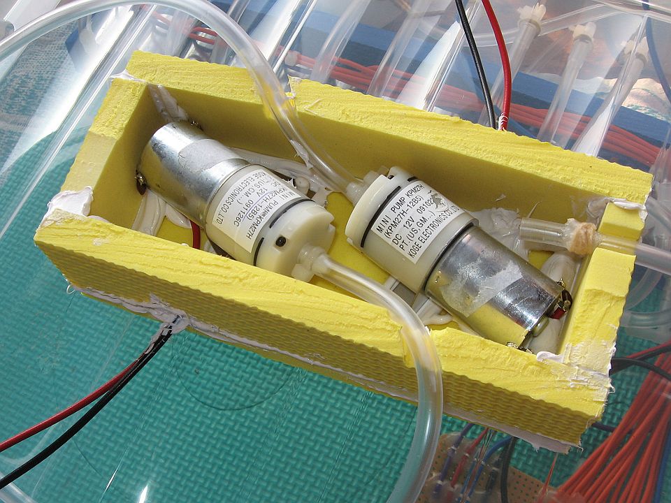
De luchtpompen maakten weinig geluid maar wel veel trilling, daardoor ging het deksel van de doos
waar het in zat trillen en geluid maken. Dus de luchtpompen heb ik vervangen door 12V luchtpompen.
Deze konden voldoende druk opbouwen (700 mbar), maar gaven te weinig lucht. Daarom deed ik er twee
parallel.
De twee luchtpompen hadden geen aansluiting voor een luchtinlaat.
Daarom plaatste ik de luchtpompen in een doos,
en een opening in die doos is dan de luchtinlaat. Ik kon echter geen kunststof doos vinden
met de juiste afmetingen, daarom maake ik zelf een doos met stevig foam (EVA foam) en ms-polymeerkit
om alles dicht te maken. Als de luchtpompen nu een luchtcompartiment leeg pompen, dan staan de wanden
van die doos hol. Maar het lijkt goed te gaan, na een jaar werkt het nog steeds.
In 2013 werkte het meeste nog goed, maar de luchtpompen konden niet veel druk meer opbouwen
en de kleppen lekten. Dat bleek nog geen probleem. Ik gebruik maar 130 mbar voor
een vol luchtcompartiment en een druk van -25 mbar om te detecteren dat het leeg is.
2014
Arduino-compatible gemaakt
In 2014 bleken na twee jaar meerdere binnenbanden lek te zijn (op de vouw aan de buitenrand van mijn
matras). Ook bleek een klep te veel te lekken. Dus ik sloot die klep af, zodat er nog maar negen
binnenbanden gebruikt zouden worden.
Om gemakkelijker wijzigingen te maken, maakte ik het Arduino-compatible. Daarvoor moest ik
het printje wat aanpassen, en de code vertalen.
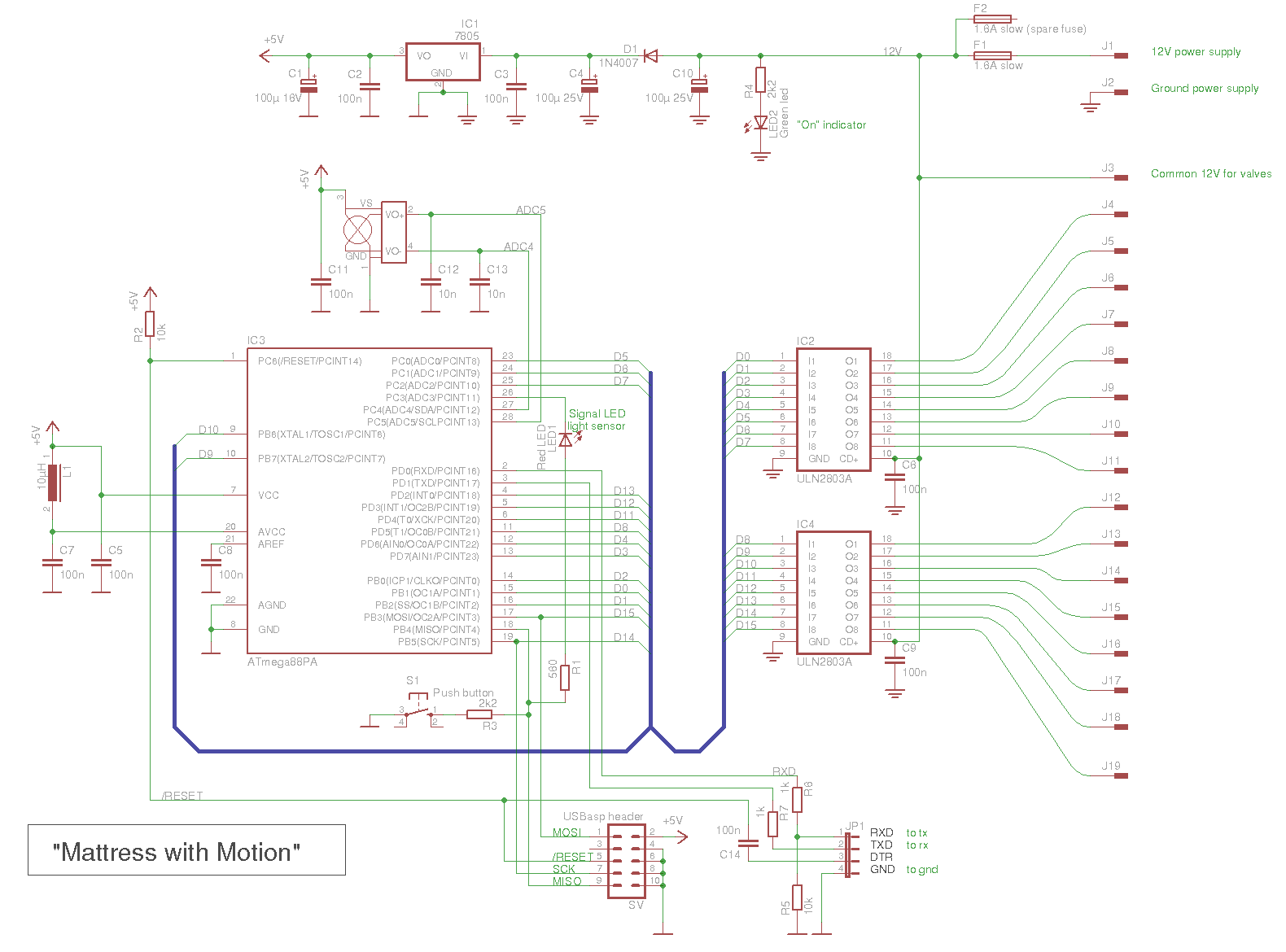
Dit is het nieuwe schema (klik op het plaatje voor een grotere versie):
De ATmega88PA is niet helemaal Arduino-compatible, maar het meeste zou werken.
De ATmega88P heeft dezelfde chip signature, maar toch koos ik er voor om alles
speciaal voor de ATmega88PA te doen.
Allereest een bootloader maken met Optiboot 5.0a.
Eerst optiboot.c aangepast, door deze regel uit te breiden:
Optiboot 5.0a bleek niet samen te gaan met Arduino 1.5.8.
Ik besloot om het "make" bestand te gebruiken om de commandoregels te laten maken,
en die commondoregels heb ik direct gebruikt om de bootloader te maken met avr-gcc 4.8.2.
Dit werden de commandregels:
part parent "m88"
    id               = "m88pa";
    desc             = "ATmega88PA";
    signature        = 0x1e 0x93 0x0f;

    ocdrev              = 1;
  ;
Omdat ik de pinnen voor het crystal gebruik als pinnen om kleppen aan te sturen,
was dat niet compatible met Arduino. Daardoor waren extra functies nodig.
Die functies zitten in het bestand "PinsExtra.ino".
Hieronder staan de zes bestanden.
Bestand: Mattress_with_Motion.ino
// Mattress with Motion
// --------------------
//
// Arduino 1.5.8 BETA
// ATmega88PA with internal 8MHz clock.
//
// Version 2.00, oktober 2014
//    Rewritten the code for Arduino.

// The internal oscillator is used, and the pins for the crystal
// are used as output pins.
//
// In the schematic the bus is called D0 to D15 for the valves.
// The Valves for the pockets are called 'Valve 1' to 'Valve 10'.
// Also the air pocket are called 'Pocket 1' to 'Pocket 9' (one valve is broken).
// In the sketch I don't use those name, I use the index starting at 0.
//
// Wiring :
//     Schematic bus D0  = Arduino pin 9      = Valve Low
//     Schematic bus D1  = Arduino pin 10     = Valve number 6  [5]
//     Schematic bus D2  = Arduino pin 8      = Valve Inlet
//     Schematic bus D3  = Arduino pin 7      = Valve number 7  [6]
//     Schematic bus D4  = Arduino pin 6      = Valve number 3  [2]
//     Schematic bus D5  = Arduino pin A0     = Valve number 5  [4]
//     Schematic bus D6  = Arduino pin A1     = Valve number 8  [7]
//     Schematic bus D7  = Arduino pin A2     = Valve number 1  [0]
//     Schematic bus D8  = Arduino pin 5      = Valve number 9  [8]
//     Schematic bus D9  = xtal pin (PB6)     = Valve High
//     Schematic bus D10 = xtal pin (PB7)     = Valve number 2  [1]
//     Schematic bus D11 = Arduino pin 4      = Valve Outlet
//     Schematic bus D12 = Arduino pin 3      = Valve number 10 [9]
//     Schematic bus D13 = Arduino pin 2      = Valve number 4  [3]
//     Schematic bus D14 = Arduino pin 13     = (not used)
//     Schematic bus D15 = Arduino pin 11     = Pump

#include "PinsExtra.h"

// The pressure sensor outputs of the bridge.
const int pinBridge1 = A5;
const int pinBridge2 = A4;

// The button is connected with 2k2 to pin 12
// pin 12 is also connected to the led with 560 ohm.
// const int pinButton = 12;
const int pinLed = 12;
const int pinLedGnd = A3;

// I used to have 10 air pockects with valves, but one valve is broken.
const int NumberValves = 10;
const int NumberPockets = 9;

// The valves to the air pockets.
const int pinValves[] = { A2, ExtraPB7, 6, 2, A0, 10, 7, A1, 5, 3 };

// Original definition for air pockets with 10 pockets
//   const int pinPocket[] PROGMEM = { A2, ExtraPB7, 6, 2, A0, 10, 7, A1, 5, 3 };
// New definition with pocket 5 removed
const int pinPocket[] = { A2, ExtraPB7, 6, 2,     10, 7, A1, 5, 3 };

const int pinInlet = 8;
const int pinOutlet = 4;
const int pinHigh = ExtraPB6;
const int pinLow = 9;
const int pinPump = 11;

void setup()
{
  Serial.begin( 9600);
  Serial.println(F("Mattress with motion"));
  Serial.println(F("Version 2.00"));

  Button_Led_init();

  // Set all valves and pump output and low.
  pinModeExtra( pinInlet, OUTPUT);
  pinModeExtra( pinOutlet, OUTPUT);
  pinModeExtra( pinHigh, OUTPUT);
  pinModeExtra( pinLow, OUTPUT);
  pinModeExtra( pinPump, OUTPUT);

  // Set all valves as output and low, broken or not.
  for( int i=0; i<NumberValves; i++)
  {
    int pin = pinValves[i];
    pinModeExtra( pin, OUTPUT);
  }
}

void loop()
{
  // Do wave in reverse order.
  // One valve is broken, so there are 9 air pockets
  // Start with [8] down to [0]
  for( int i=(NumberPockets-1); i>=0; i--)
  {
    WaveNext( i);
  }
}
Bestand: Button_Led.ino
static boolean ledOn;

void Button_Led_init()
{
  // The button is connected with 2k2 to pin 12
  // pin 12 is also connected to the led with 560 ohm.
  pinMode( pinLed, OUTPUT);
  pinMode( pinLedGnd, OUTPUT);

  digitalWrite( pinLed, LOW);
  digitalWrite( pinLedGnd, LOW);

  ledOn = false;
}

void Led( boolean On)
{
  if( On)
  {
    digitalWrite( pinLed, HIGH);
  }
  else
  {
    digitalWrite( pinLed, LOW);
  }
  ledOn = On;
}

boolean Button()
{
  boolean pressed;

  // The led is connected to the button.
  // Use the same pin and restore the led.
  pinMode( pinLed, INPUT_PULLUP);
  pinMode( pinLedGnd, INPUT);

  delay(1); // wait 1ms for slow rise with pullup

  if( digitalRead( pinLed) == LOW)
    pressed = true;
  else
    pressed = false;

  // restore the Led to its previous state
  pinMode( pinLedGnd, OUTPUT);
  digitalWrite( pinLedGnd, LOW);
  pinMode( pinLed, OUTPUT);
  Led( ledOn);         // use function to restore led to its state

  return( pressed);
}
// PinsExtra
// ---------
//
// The extra pins that are combined with the crystal pins.
// They are on the ATmega8, ATmega168, ATmega328P.
// They can be used when the internal clock is selected
// (a special bootloader and boards definition is needed for that).
// The ATmega32U4 and ATmega2560 don't have the extra pins,
// since the crystal pins are not shared with digital pins.

#include "PinsExtra.h"

// const int ExtraOffset = 115;
// const int ExtraPB6 = (PB6 + ExtraOffset);
// const int ExtraPB7 = (PB7 + ExtraOffset);

void digitalWriteExtra( byte pin, byte level)
{
  if( pin == ExtraPB6 || pin == ExtraPB7)
  {
    byte ATmegaPin = pin - ExtraOffset;
    bitWrite( PORTB, ATmegaPin, level);
  }
  else
  {
    digitalWrite( pin, level);
  }
}

byte digitalReadExtra( byte pin)
{
  if( pin == ExtraPB6 || pin == ExtraPB7)
  {
    byte ATmegaPin = pin - ExtraOffset;
    return bitRead( PINB, ATmegaPin);
  }
  else
  {
    return digitalRead( pin);
  }
}

void pinModeExtra( byte pin, byte mode)
{
  if( pin == ExtraPB6 || pin == ExtraPB7)
  {
    byte ATmegaPin = pin - ExtraOffset;
    switch( mode)
    {
    case INPUT:
      bitClear( DDRB, ATmegaPin);
      bitClear( PORTB, ATmegaPin);  // remove pullup
      break;
    case INPUT_PULLUP:
      bitClear( DDRB, ATmegaPin);
      bitSet( PORTB, ATmegaPin);  // enable pullup
      break;
    case OUTPUT:
      bitSet( DDRB, ATmegaPin);
      break;
    }
  }
  else
  {
    pinMode( pin, mode);
  }
}
Bestand: Pressure.ino
// Get the pressure of the 'main' line.
// in mbar

const int nAvg = 5;

int getPressure()
{
  int x;

  x = 0;
  for( int i=0; i<nAvg; i++)
  {
    // The calculation is not accurate,
    // the value is more like a rough indication.
    x += analogRead( pinBridge2) - analogRead( pinBridge1);
  }
  int mbar = (25 * x) / nAvg;
  return( mbar);
}
Bestand: Wave.ino
// This function performs the way the air pockets are
// inflated and deflated.
// The is no logic to it, after a while this sequence seems okay.

// The delay between switching the valves, to reduce noise.
const int vDelay = 180;

void WaveNext(int pocket)
{
  // 'previousPocket' is the previous pocket.
  // It is used to pass air from previous pocket to next pocket
  // Therefor the value is remembered, and declared 'static'.
  static int previousPocket = 0;
  boolean PressureReached;

  int pinPrev = pinPocket[previousPocket];
  int pin = pinPocket[pocket];

  // Set the previous pocket air on the main line
  digitalWriteExtra( pinPrev, HIGH);
  delay( 500);

  // Check remaining pressure that was in the previous inflated air pocket.
  // It is an indication of the leaks.
  Serial.print( F("Pocket (1..."));
  Serial.print( NumberPockets);
  Serial.print( F(") "));
  Serial.print( previousPocket + 1);
  Serial.print( F(", Remaining "));
  Serial.print( getPressure());
  Serial.println( F(" mbar"));

  // Open the valve to the new pocket
  // Some air can flow from the previous to the new.
  digitalWriteExtra( pin, HIGH);
  delay(5000);

  // Close previous pocket
  digitalWriteExtra( pinPrev, LOW);
  delay( vDelay);

  // Set inlet via pump via high valve to main line
  // The new pocket will be inflated
  // The valve to the new pocket is still open.
  digitalWriteExtra( pinHigh, HIGH);
  delay( vDelay);
  digitalWriteExtra( pinInlet, HIGH);
  delay( vDelay);
  digitalWriteExtra( pinPump, HIGH);
  delay( vDelay);

  // wait half a second to let pressure settle.
  delay( 500);

  // pressure in mbar, timeout in seconds.
  PressureReached = inflatePocket( 145, 37);

  // The timeout could be an indication of a loose tube
  if( !PressureReached)
  {
    Serial.print( F("Inflate timeout at pocket "));
    Serial.println( pocket + 1);   // Pocket number 1 is the first
  }

  // Get air out of the previous pocket
  digitalWriteExtra( pinPump, LOW);
  delay( vDelay);
  digitalWriteExtra( pin, LOW);
  delay( vDelay);
  digitalWriteExtra( pinHigh, LOW);
  delay( vDelay);
  digitalWriteExtra( pinInlet, LOW);
  delay( vDelay);
  digitalWriteExtra( pinLow, HIGH);
  delay( vDelay);
  digitalWriteExtra( pinOutlet, HIGH);
  delay( vDelay);
  digitalWriteExtra( pinPrev, HIGH);
  delay( vDelay);
  digitalWriteExtra( pinPump, HIGH);
  delay( vDelay);

  // wait half a second to let pressure settle.
  delay( 500);

  // pressure in mbar, timeout in seconds.
  PressureReached = deflatePocket( -25, 28);

  // The timeout could be an indication of a loose tube
  if( !PressureReached)
  {
    Serial.print( F("Deflate timeout at pocket "));
    Serial.println( previousPocket + 1);   // Pocket number 1 is the first.
  }

  digitalWriteExtra( pinPump, LOW);
  delay( vDelay);
  digitalWriteExtra( pinOutlet, LOW);
  delay( vDelay);
  digitalWriteExtra( pinLow, LOW);
  delay( vDelay);
  digitalWriteExtra( pinPrev, LOW);
  delay( vDelay);

  // Remove any negative pressure in the main line.
  digitalWriteExtra( pinInlet, HIGH);
  delay( vDelay);
  digitalWriteExtra( pinLow, HIGH);
  delay( 500);

  // Close everything
  digitalWriteExtra( pinInlet, LOW);
  delay( vDelay);
  digitalWriteExtra( pinLow, LOW);
  delay( vDelay);

  // remember this pocket for the next time
  previousPocket = pocket;
}

boolean inflatePocket( int pressure, int timeout)
{
  // The timeout is in seconds, but I want to stop immediately when
  // the pressure is reached.
  // So the millis() is used for timing.
  // Prevent rollover trouble by using unsigned long for substraction.
  unsigned long previousMillis = millis();
  unsigned long t = (unsigned long) timeout * 1000UL;

  while( millis() - previousMillis < t)
  {
    if( getPressure() > pressure)
      return( true);
  };
  return( false);       // pressure not reached, timeout
}

boolean deflatePocket( int pressure, int timeout)
{
  unsigned long previousMillis = millis();
  unsigned long t = (unsigned long) timeout * 1000UL;

  while( millis() - previousMillis < t)
  {
    if( getPressure() < pressure)
      return( true);
  };
  return( false);       // pressure not reached, timeout
}
2018
In 2018 helpt mijn matras met beweging minder goed voor mijn rug.
Het bleek dat één van de pompjes het niet meer deed.
Het doosje waarin de pompjes zaten, gemaakt van EVA schuim
en ms-polymeer kit, was na al die jaren nog steeds luchtdicht.
Ik gebruik de laatste jaren betere fietsbanden die langer meegaan,
maar daar zit talkpoeder in.
Dat talkpoeder kwam bij de kleppen die het daardoor niet goed meer doen.
Om de minder goed werkende kleppen te compenseren, deed ik er een sterkere
luchtpomp in. Een ULN2803A had nog een ongebruikte uitgang, die gebruikte ik
parallel met de uitgang van de pomp zodat de sterkere pomp aangestuurd kon worden.
Daarna werkte mijn matras met beweging weer een stuk beter, maar toch nog niet zo goed
als in het begin.
Rechten: Het filmpje over mijn "Matras met Beweging"
en de foto's en tekeningen en programma code
op deze bladzijde zijn door mij gemaakt
en zijn Public Domain, tenzij anders vermeld.