First idea: about the year 2000
Tried alternating pressure mattress: 2009 ... 2011
First version of my homemade mattress with motion: 2012
For many years I had the idea to keep my back and neck in motion during sleeping.
Because I only can lie on my back due to my neck problems, I lie too motionless
during sleeping. So I wanted a mattress with active motion.
I talked about it with others and I even placed an advertisement in a local newspaper
to ask others for help.
In the end, that didn't lead to any result.
I tried an alternating pressure mattress
to keep my spine in motion while I am sleeping.
That was not a success, because it was too much motion for my neck.
There are devices on the market with a vibrating motor for massage,
but I want to keep my spine in motion with small and slow motions.
So I decided to make something myself.
I took me a lot of effort, and I often wandered if it would ever pay off.
But only after a week with a first test, it turned out to have a positive effect.
A mechanical construction would become complicated.
With air pockets and air pressure it would be easier and that is also safe.
During making my mattress with motion, I didn't know what the final result would look like.
I thought that I would need somewhere between 2 to 40 air pockets,
and I want to able to program each air pocket individually when they would inflate or deflate.
I tested a few pumps and a few solenoid valves.
For my tests I used a flow meter, and a pressure sensor.
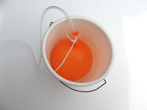
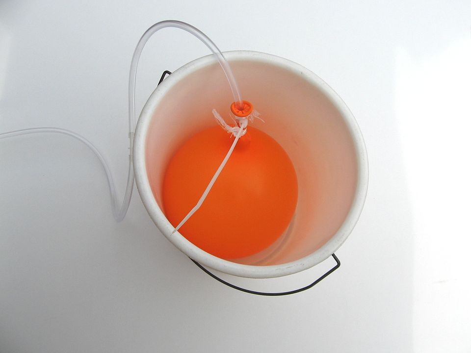
Flow meter
To measure the air flow of the pumps, I needed a air flow meter.
I used the "balloon-in-the-bucket" flow meter.
I put an empty balloon in a bucket, en let the air flow inflate the balloon.
As soon as the balloon is stuck in the bucket, I stop the stopwatch.
The time to fill the balloon can be converted in liters per minute.
The back pressure of the balloon was not that much (40 mbar).
My measurements with the "balloon-in-the-bucket" method turned out to be not reliable.
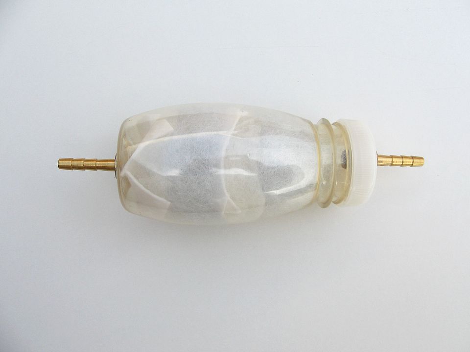
So later I used an air compartment of non-elastic material (PVC).
I first immersed it in water, to determine the contents. It turned out to be 2.4 liter.
From then on, I just measured the time until is was completely filled.
That greatly improved my measurements.
There are also air flow meters, which are used in cars.
They are quite expensive, but also used ones are available.
I didn't buy one, because measuring the air flow was not that important anyway.
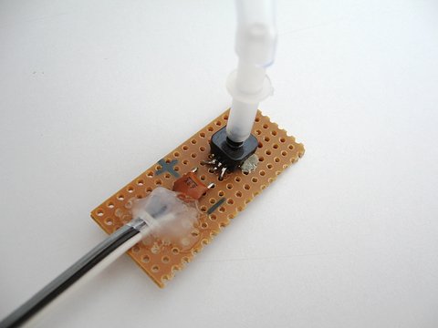
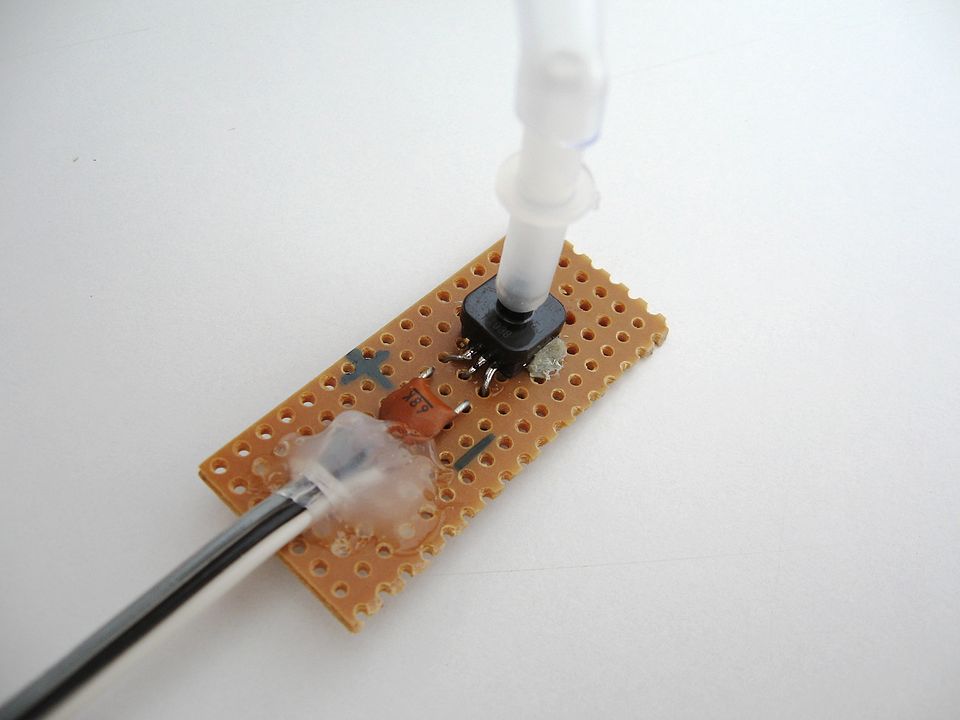
Pressure sensor
To measure the pressure, I would need a pressure meter that is able to measure
both positive pressure and negative pressure (vacuum).
The MPXH6400A sensor could do that. It works at 5V and measures the absolute pressure.
It is therefor also a barometer.
The output is an analog signal. It can measure from -0.8 bar to 3 bar.
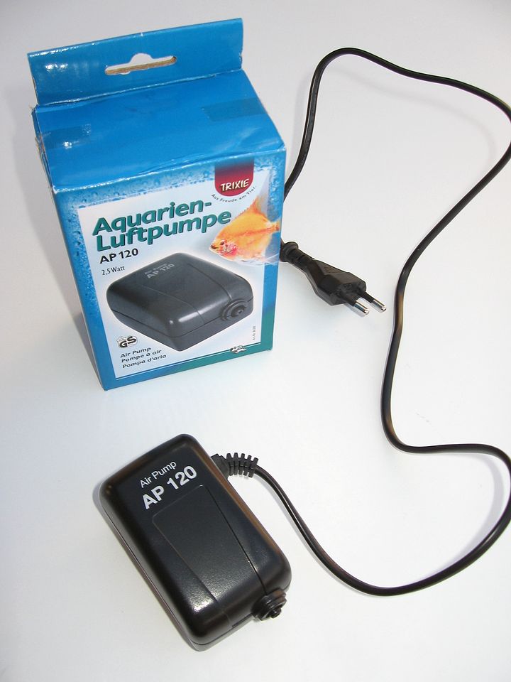
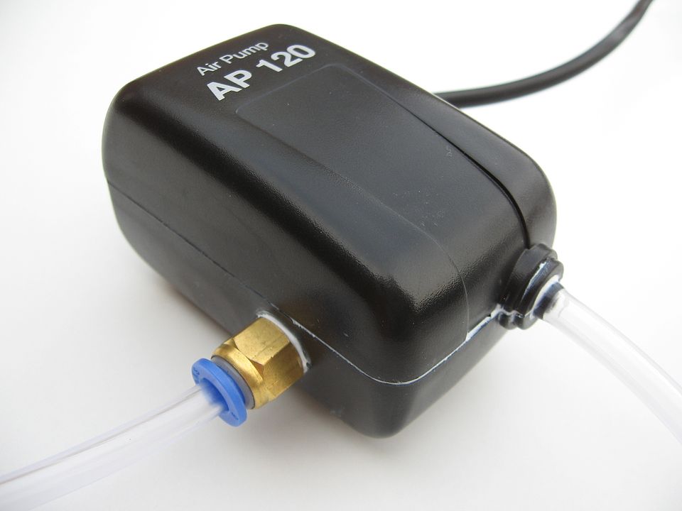
After some tests I found out that some aquarium pumps almost supply enough pressure.
I choose a good aquarium pump, those are mechanical and electrical of much better
quality than the cheap ones.
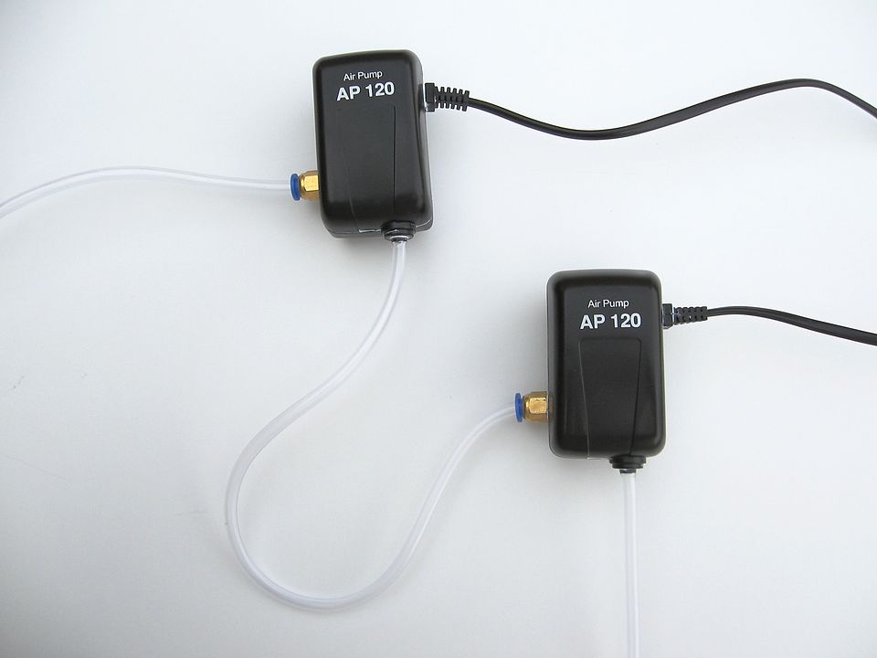
To get more pressure, I used two aquarium pumps to double the pressure.
Good aquarium pumps are silent and they last for many years. That is exactly what I needed.
Some aquarium pumps were able to deliver 0.2 bar pressure.
By cascading them I had 0.4 bar pressure, which turned out to be well enough.
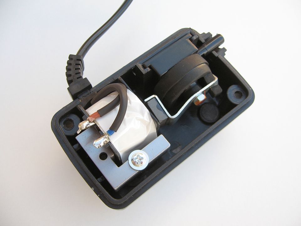
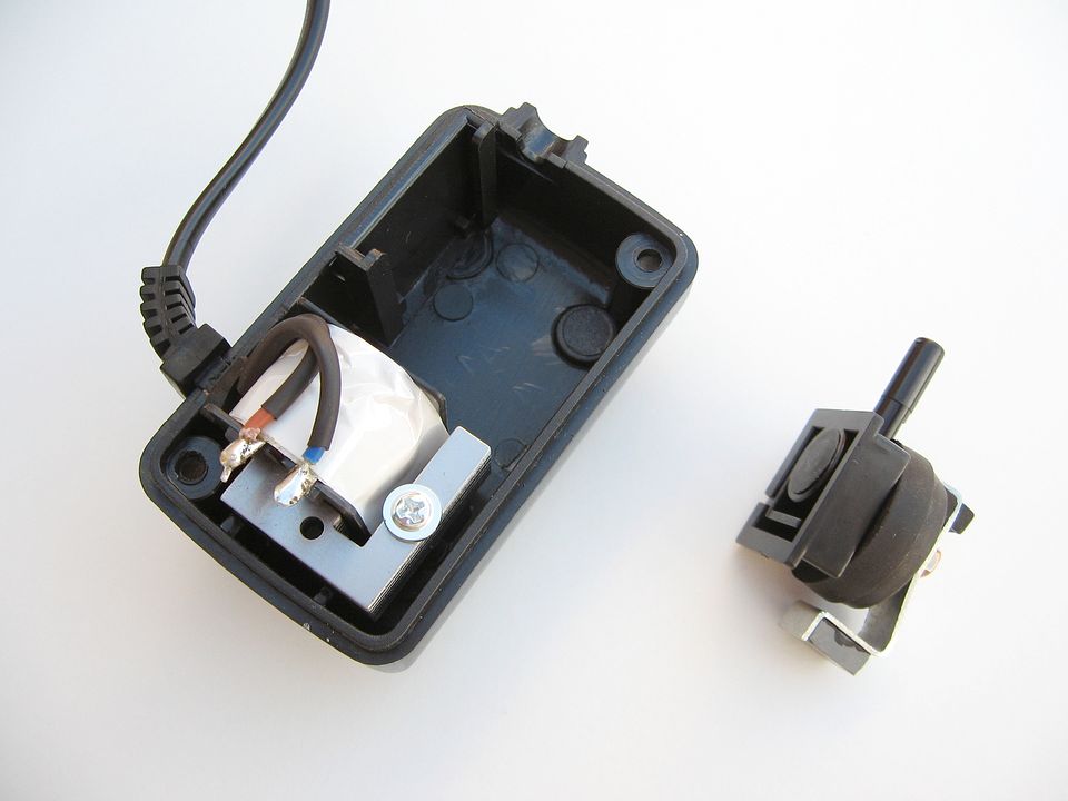
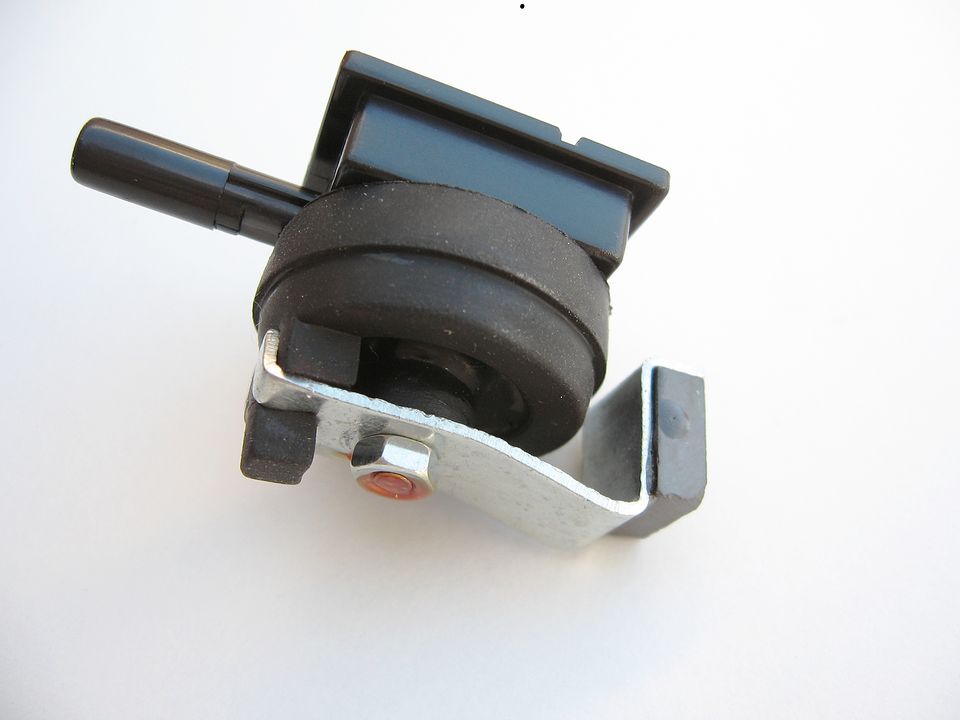
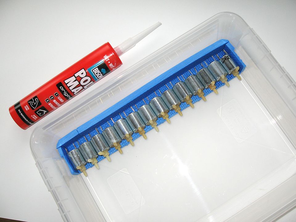
To cascade two pumps, I had to make an air inlet in the pumps.
I made the inlet in the case, and I sealed the case with sealant.
Because I made an inlet, I now have to use a air filter to keep
the pumps clean.
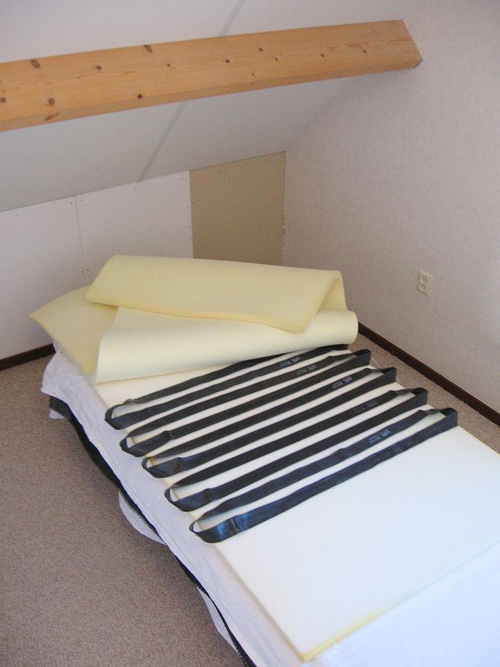
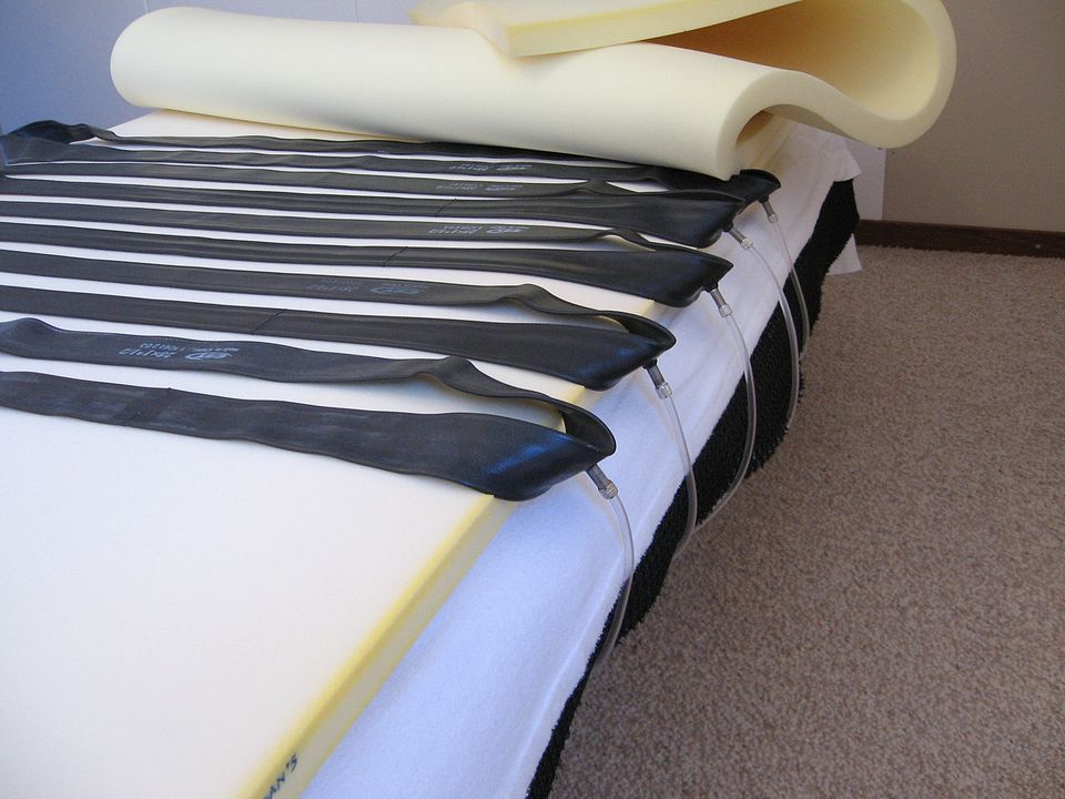
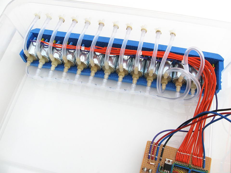
Because I used my mattress with layers,
I could place the air pockets between the layers of my mattress.
I used bicycle inner tubes as air pockets.
The rubber of the bicycle inner tubes is actually too thick, and this influences the mattress.
Something better for the air pockets is hard to find.
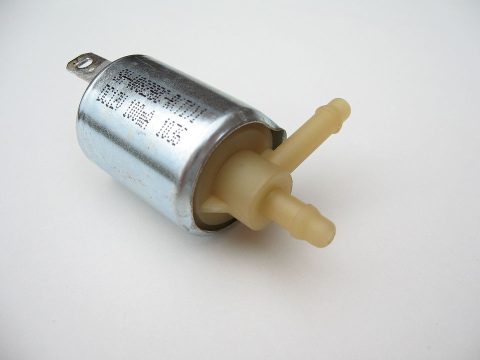
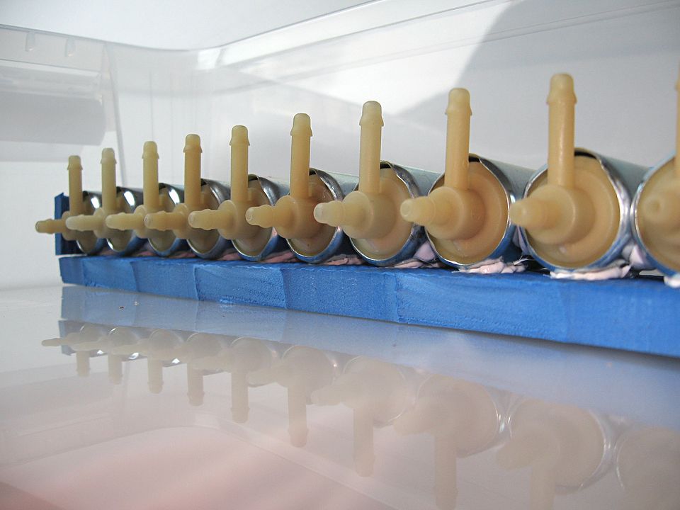
I was able to buy used solenoid valves which were ideal for the low pressure
and low airflow that I use.
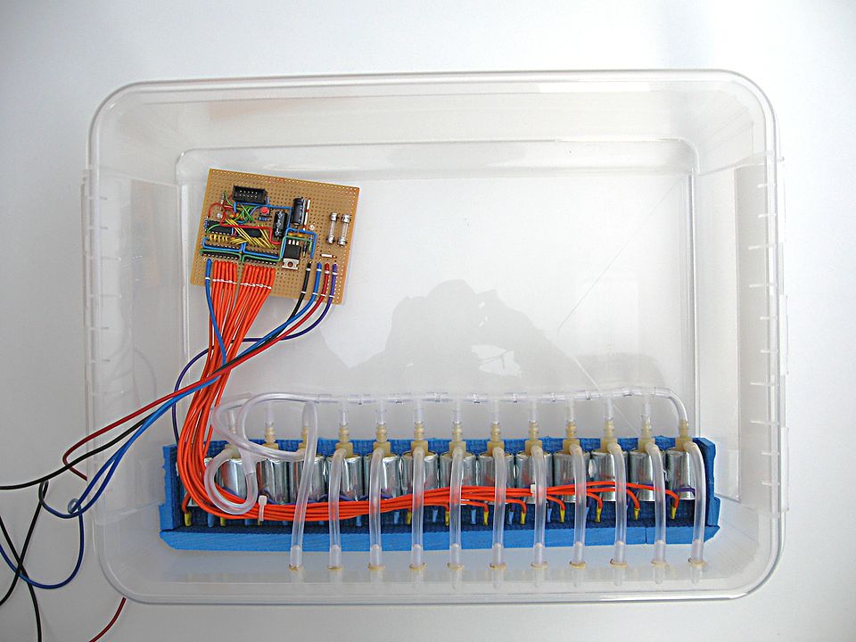
Fourteen valves fitted in the box that I bought for the control unit.
The box was marked on the bottom as "PP-05". This means that it is made from polypropylene.
If I would drill holes in, it would crack and break.
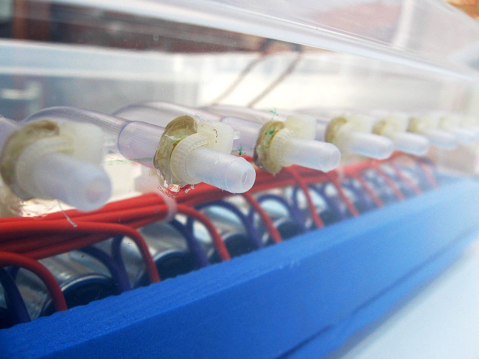
So I made a drill bit hot over a flame and used it to make holes
for the connectors for the tubes.
To be able to inflate or deflate all valves simultaneously,
I would need two main lines: one line for a positive pressure
and a line for negative pressure (vacuum).
But then two valves would be needed for each air compartment,
to be able to choose between the two main lines.
That makes everything more complicated.
I want at least to use the pump to make the air compartments completely
empty, so no air is left behind in the air compartments.
So I chose to use just one valve per air compartment,
and they all are connected to one main line.
But then I needed 4 valves to be able to use the pump to
inflate or deflate the air compartments.
Perhaps less valves is possible,
but to me it seems better not to let an reverse airflow go through
the air filter.
The valves are suitable for an air flow in only one direction.
The inlet of the valve can withstand more pressure, and leak the least.
When connecting the valves, I didn't care much about the direction of the airflow through the valves,
but more on which side of the valve can withstand air pressure.
This is how the valves are connected (click on the image for a larger version):
The plus-sign indicates the side of the valves that can withstand pressure.
To control everything, I needed something that I could program.
The best choice is an AVR micro-controller, since there are many examples on the internet
and many people are willing to help.
The Arduino is meant for such things, but both the hardware and
software was too complicated for me.
It was my job to write software to be used in devices.
But due to my neck problems it took me a lot more
effort to do such things. What I used to do in one day,
takes me more than a week (and only if I was fit enough for it).
Therefor I started with a ATtiny13 microprocessor.
Eventually I was able to make a blinking led with it.
From that point I could go on.
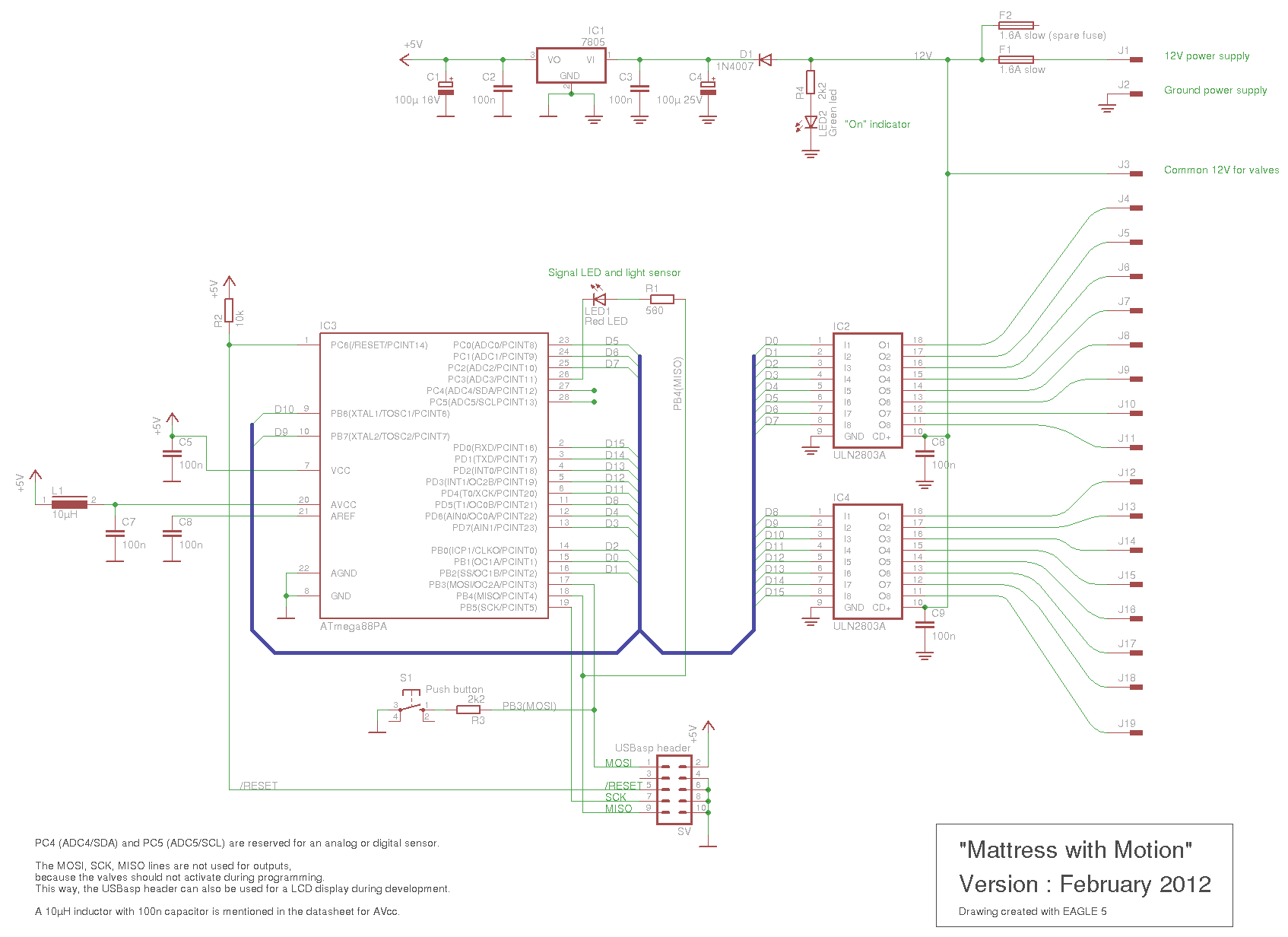
The control unit has to be as simple as possible to make.
I came up with the next design (click on the image for a larger version):
I choose these parts:
• ATmega88
The ATmega88 is a newer version of the ATmega8.
It's got enough pins to control my 14 valves.
It has 8kbyte memory, which should be well enough.
I used a ATmega88PA, which has an internal temperature sensor.
• ULN2803A
To control the valves, I could use transistors (for example BC639)
or "logic level" MOSFETs.
The ULN2803A however, makes things a lot easier.
The valves are 100mA, which is well within the specifications of the ULN2803A.
No extra components are needed to keep the valves off during power-up.
• 7805
The 5V voltage regulator is without cooling,
because only little current is used.
• Signal LED and light sensor
A LED can be used as a light sensor.
That's why the LED (with a resistor) is between two pins of the ATmega88.
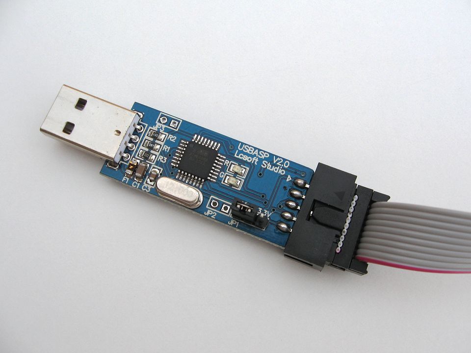
• USBasp
To program it, I use a USBasp connection.
A USBasp programmer costs only 3 euros.
As shown in the schematic, there are two types of ground.
That is because I want to have the possibility to connect an analog sensor,
and I don't want the current through the valves to influence the analog section.
Therefore I separated the grounds. They are connected at the 7805 voltage regulator.
This is such a USBasp programmer:
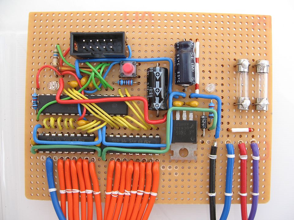
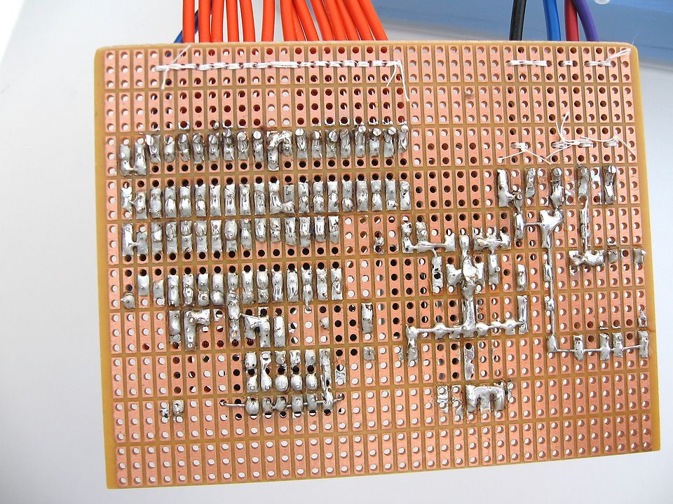
I did not manage to create a PCB design with a program.
So I soldered everything with wires.
I had to do small steps over a few weeks of time to be able to finish it.
If I ever want more air pockets, then I will have to let a PCB be made for me.
Below is the source code ("mattress.c"):
// ------------------------------------------------
//
//  "Mattress with Motion"
//
//  File    : mattress.c
//  Version : February 2012
//
//  Using the ATmega88PA with ULN2803A drivers.
//  A led is connected between two pins,
//  to be able to use it also as a light sensor.
//  A switch is in the hardware, but not used yet.
//
//  With avr-gcc 4.3.5 in Linux Mint 11 and avrdude 5.10.
//

// The ATmega88PA runs default at 1MHz,
// but can be set to 8MHz with a fuse.
#define F_CPU 1000000UL

#include <avr/io.h>
#include <stdbool.h>
#include <stdlib.h>
#include <util/delay.h>
#include <avr/pgmspace.h>


// To set or clear a bit in a register, I use my own macro's.
#define BIT_SET(port,bit) port |= _BV(bit)
#define BIT_CLEAR(port,bit) port &= ~_BV(bit)
#define BIT_TEST(port,bit) (port & _BV(bit))
#define BIT_INVERT(port,bit) port ^= _BV(bit)

#define TRUE true
#define FALSE false


// Hardware specific definitions
#define SWITCH PB3
#define LED PB4
#define LED_GROUND PC3

// There are 14 valves.
// One output is used to switch the pump on and off.
// So one output is not used and is a spare.
// The wires of the valves are soldered without checking the output number.
// How the valves and air pockets are connected to the outputs is solved by software.

// The next definitions define all the valves and the pump.
// The order is not hardware related.
// The order is only for an index of the valve[][2] array.
enum output_names
{
  VALVE_1 = 0,
  VALVE_2,
  VALVE_3,
  VALVE_4,
  VALVE_5,
  VALVE_6,
  VALVE_7,
  VALVE_8,
  VALVE_9,
  VALVE_10,
  VALVE_OUTLET,
  VALVE_HIGH,
  VALVE_INLET,
  VALVE_LOW,
  PUMP,
  SPARE,
};


// The next definitions define how the air pockets are connected the valves.
// Most of the time, the first pocket is connected to the first valve, and so on.
enum air_pockets
{
  POCKET_1 = VALVE_1,
  POCKET_2 = VALVE_2,
  POCKET_3 = VALVE_3,
  POCKET_4 = VALVE_4,
  POCKET_5 = VALVE_5,
  POCKET_6 = VALVE_6,
  POCKET_7 = VALVE_7,
  POCKET_8 = VALVE_8,
  POCKET_9 = VALVE_9,
  POCKET_10 = VALVE_10,
};


// PORTB can not be used in a constant, because PORTB is a define with calculation.
// So define it with normal values to indicate the port.
enum port_defines
{
  _PORT_A,
  _PORT_B,
  _PORT_C,
  _PORT_D,
};


// Connections of valves.
// The next constant array is located in program code with 'PROGMEM'.
// It translates the definitions for the valves to the hardware connections.
// Both the order and the values should match the hardware.
const unsigned char valve[][2] PROGMEM =
{
  {_PORT_B, PB0},     //  VALVE_1
  {_PORT_B, PB1},     //  VALVE_2
  {_PORT_B, PB2},     //  VALVE_3
  {_PORT_B, PB6},     //  VALVE_4
  {_PORT_B, PB7},     //  VALVE_5
  {_PORT_C, PC0},     //  VALVE_6
  {_PORT_C, PC1},     //  VALVE_7
  {_PORT_C, PC2},     //  VALVE_8
  {_PORT_D, PD0},     //  VALVE_9
  {_PORT_D, PD1},     //  VALVE_10
  {_PORT_D, PD2},     //  VALVE_OUTLET
  {_PORT_D, PD3},     //  VALVE_HIGH
  {_PORT_D, PD4},     //  VALVE_INLET
  {_PORT_D, PD5},     //  VALVE_LOW
  {_PORT_D, PD6},     //  PUMP
  {_PORT_D, PD7},     //  SPARE
};


// defines for valves and pump.
#define OPEN true
#define CLOSE false
#define ON true
#define OFF false


// ###########################################################
// Delay functions
//
// The library functions _delay_ms and _delay_us
// can only delay for about 20 ... 200.
// The actual maximum depends on the frequency of the chip.
// So a workaround should always be added.
// The slight overhead adds some extra delay.

void delay_ms (uint16_t milliseconds)
{
  while ( milliseconds )
  {
    _delay_ms (1);
    milliseconds--;
  }
}

void delay_s (uint16_t seconds)
{
  while (seconds)
  {
    delay_ms(1000);
    seconds--;
  }
}


// ###########################################################
// Function Valve
//
// This function translates the requested valve to the hardware output.
// A valve is closed (or off) if not activated.
// Turning it 'ON' or 'OPEN' activates the output and activates the valve.
// This function can be used with either VALVE_1, or PUMP, and also with POCKET_1, etc.
// The second parameter can be TRUE, FALSE, ON, OFF, OPEN, CLOSE.

void Valve (uint8_t byteValve, uint8_t byteOpen)
{
  uint8_t portdef, pin;
  volatile uint8_t *pPort=NULL;

  portdef = pgm_read_byte (&valve[byteValve][0]);
  pin     = pgm_read_byte (&valve[byteValve][1]);

  // Translate the definition for the port to the actual io-port.
  // Since 'PORTB' is the actual port in the io-register area,
  // using a pointer seems to be the best way to do this.
  switch (portdef)
  {
  case _PORT_B:
    pPort = &PORTB;
    break;
  case _PORT_C:
    pPort = &PORTC;
    break;
  case _PORT_D:
    pPort = &PORTD;
    break;
  }

  if (pPort != NULL)
  {
    // Set the valve (or pump).
    if (byteOpen)
    {
      BIT_SET (*pPort, pin);
    }
    else
    {
      BIT_CLEAR (*pPort, pin);
    }
  }
}


// ###########################################################
// Function SlowWave_Next
//
// A sequence for the air pockets.
// This sequence is a slow wave.
// A static variable is used to remember the previous air pocket.
// This way some of the pressurized air can be used for the next air pocket.
//
// This function assumes that all valves and the pump are off.

void SlowWave_Next (uint8_t nNewPocket)
{
  static uint8_t nOldPocket = POCKET_1;

  // Let the pressure flow to new air pocket.
  Valve (nOldPocket, OPEN);
  Valve (nNewPocket, OPEN);
  delay_s (10);

  // let first one deflate.
  Valve (nNewPocket, CLOSE);
  Valve (VALVE_HIGH, OPEN);
  Valve (VALVE_OUTLET, OPEN);
  delay_s (10);
  Valve (VALVE_HIGH, CLOSE);
  Valve (VALVE_OUTLET, CLOSE);
  Valve (nOldPocket, CLOSE);

  // Pressurize second one further.
  Valve (VALVE_HIGH, OPEN);
  Valve (VALVE_INLET, OPEN);
  Valve (PUMP, ON);
  Valve (nNewPocket, OPEN);
  delay_s (50);

  // Deflate first one further, using the pump.
  Valve (nNewPocket, CLOSE);
  Valve (VALVE_HIGH, CLOSE);
  Valve (VALVE_INLET, CLOSE);
  Valve (nOldPocket, OPEN);
  Valve (VALVE_LOW, OPEN);
  Valve (VALVE_OUTLET, OPEN);
  delay_s (10);

  // Hold pressure in the second one.
  Valve (PUMP, OFF);
  Valve (VALVE_LOW, CLOSE);
  Valve (VALVE_OUTLET, CLOSE);
  Valve (nOldPocket, CLOSE);
  delay_s (40);

  nOldPocket = nNewPocket;
}


// ###########################################################
// main

int main(void)
{
  uint8_t i;


  // The next code is very hardware specific.
  //    The code could be like this:
  //      PORTB = 0xC7;
  //    Or the definitions of valve[][] could be used,
  //    but that would add extra program code.
  DDRB = 0xC7;                        // Select pins for output
  DDRC = 0x07;                        // Select pins for output
  DDRD = 0xFF;                        // Select pins for output

  // The next code is normal code, for the led and switch.
  BIT_SET (DDRB, LED);                // make it output
  BIT_SET (DDRC, LED_GROUND);         // make it output
  BIT_CLEAR (DDRB, SWITCH);           // make it input.
  BIT_SET (PORTB, SWITCH);            // activate internal pull-up resistor

  BIT_CLEAR (PORTC, LED_GROUND);      // make ground for led a '0'.

  // The best sequence for the air pockets is just a wild guess.
  // At this moment there is only one sequence: a slow wave.
  // This slow wave is done with the first 5 air pockets.

  while (1)
  {
    for (i = POCKET_1; i <= POCKET_5; i++)
    {
      SlowWave_Next (i);
    }
  }
}
This is the script to compile, link and programming the firmware into the avr chip ("go.sh"):
# ------------------------------------------------
#
#  "Mattress with Motion"
#
#  File    : go.sh
#  Version : February 2012
#
#
#  With avr-gcc 4.3.5 in Linux Mint 11 and avrdude 5.10.
#

avr-gcc -Wall -Os -mmcu=atmega88pa -c mattress.c
avr-gcc -mmcu=atmega88pa -o mattress.elf mattress.o
avr-objcopy -j .text -j .data -O ihex mattress.elf mattress.hex

# The ATmega88PA is not yet in the database of avrdude 5.10
# So use the ATmega88, with the (dangerous) flag '-F'.
# The new avrdude 5.11 does support the atmega88p.

sudo avrdude -c usbasp -p atmega88 -F -U flash:w:mattress.hex

# Show memory usage
avr-size -C --mcu=atmega88pa mattress.elf
The sequence for the air compartments to inflate and deflate is now programmable.
Perhaps I will make a number of sequences, and perhaps I will change between them.
Maybe a random sequence is also something to try.
By using my trolley-computer
I can program the sequence while I am lying in bed, and I can try it right away.
In 2012 I made already some changes.
I tried a number of different air compartments, but they were not strong enough.
So eventually I used ten bicycle tires.
The program was changed to run the sequence faster,
because with ten bicycle tires a cycle lasted too long.
I added a pressure sensor, so the bike tires were inflated
and deflated to a certain pressure.
I placed the pressure sensor in the "Main Line", that is the central point where all the
valves to the air compartments are connected.
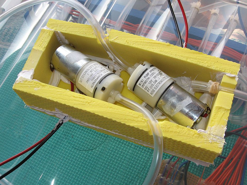
The air pumps made only little noise but they did vibrate, that made the cover of the box
in which it was to vibrate and making noise. So I replaced the air pumps with 12V air pumps.
Those could build up sufficient pressure (700 mbar), but gave too little air.
So I used two of them parallel.
The two air pumps didn't have a connection for an air inlet.
Therefore I placed the air pumps in a box,
and an opening in the box would be the air inlet.
I could not find a plastic box with the right dimensions,
therefore I made a box of foam rubber (EVA foam) and I used ms-polymer sealant/kit
to seal it. When the air pumps empty an air compartment with (a slight) vacuum,
the walls are of that box are pulled hollow.
But it seems to be going well and after a year it still works.
In 2013, the majority still worked well, but the air pumps were not able to build up
a lot of pressure and the valves leaked. That was not a problem yet. I use only 130 mbar for
a fully inflated air compartment and a pressure of -25 mbar to detect that it is empty.
2014
Making it Arduino compatible
In 2014 a number of bicycle inner tubes turned out to be leaking
(on the side of the mattress, where the tube is folded).
Also one valve was leaking too much to be used anymore.
So I closed that valve, and now only nine bicycle inner tubes could be used.
To make it easier to make changes, I made it Arduino compatible.
I had to make some adaptions to the circuit board, and I had to
translate the code to Arduino code.
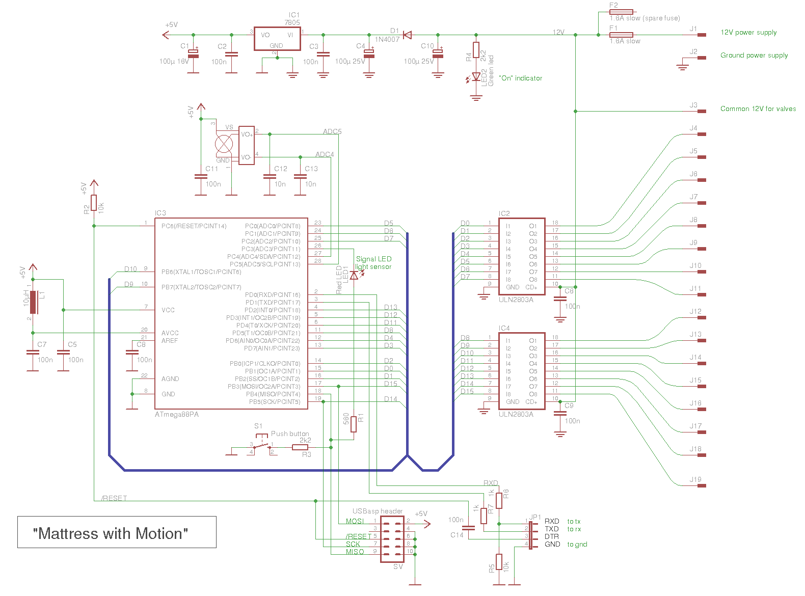
This is the new schematic (click on the picture for a larger schematic):
The ATmega88PA is not fully Arduino compatible, but most should work.
The ATmega88P has the same chip signature, but I choose to do everything
special for the ATmega88PA.
First I needed a bootloader, I used Optiboot 5.0a.
The file optiboot.c was extended by adding the ATmega88PA to this line:
Optiboot 5.0a didn't work with Arduino 1.5.8.
So I decided to use the "make" file to let it generate the command lines,
and I used those command lines to create a bootloader with avr-gcc 4.8.2.
These are the command lines:
part parent "m88"
    id               = "m88pa";
    desc             = "ATmega88PA";
    signature        = 0x1e 0x93 0x0f;

    ocdrev              = 1;
  ;
Because I use the pins for the crystal as normal digital output pins,
it was not Arduino compatible. So I used extra functions for that.
Those functions are in the file "PinsExtra.ino".
Below are the six files.
Bestand: Mattress_with_Motion.ino
// Mattress with Motion
// --------------------
//
// Arduino 1.5.8 BETA
// ATmega88PA with internal 8MHz clock.
//
// Version 2.00, oktober 2014
//    Rewritten the code for Arduino.

// The internal oscillator is used, and the pins for the crystal
// are used as output pins.
//
// In the schematic the bus is called D0 to D15 for the valves.
// The Valves for the pockets are called 'Valve 1' to 'Valve 10'.
// Also the air pocket are called 'Pocket 1' to 'Pocket 9' (one valve is broken).
// In the sketch I don't use those name, I use the index starting at 0.
//
// Wiring :
//     Schematic bus D0  = Arduino pin 9      = Valve Low
//     Schematic bus D1  = Arduino pin 10     = Valve number 6  [5]
//     Schematic bus D2  = Arduino pin 8      = Valve Inlet
//     Schematic bus D3  = Arduino pin 7      = Valve number 7  [6]
//     Schematic bus D4  = Arduino pin 6      = Valve number 3  [2]
//     Schematic bus D5  = Arduino pin A0     = Valve number 5  [4]
//     Schematic bus D6  = Arduino pin A1     = Valve number 8  [7]
//     Schematic bus D7  = Arduino pin A2     = Valve number 1  [0]
//     Schematic bus D8  = Arduino pin 5      = Valve number 9  [8]
//     Schematic bus D9  = xtal pin (PB6)     = Valve High
//     Schematic bus D10 = xtal pin (PB7)     = Valve number 2  [1]
//     Schematic bus D11 = Arduino pin 4      = Valve Outlet
//     Schematic bus D12 = Arduino pin 3      = Valve number 10 [9]
//     Schematic bus D13 = Arduino pin 2      = Valve number 4  [3]
//     Schematic bus D14 = Arduino pin 13     = (not used)
//     Schematic bus D15 = Arduino pin 11     = Pump

#include "PinsExtra.h"

// The pressure sensor outputs of the bridge.
const int pinBridge1 = A5;
const int pinBridge2 = A4;

// The button is connected with 2k2 to pin 12
// pin 12 is also connected to the led with 560 ohm.
// const int pinButton = 12;
const int pinLed = 12;
const int pinLedGnd = A3;

// I used to have 10 air pockects with valves, but one valve is broken.
const int NumberValves = 10;
const int NumberPockets = 9;

// The valves to the air pockets.
const int pinValves[] = { A2, ExtraPB7, 6, 2, A0, 10, 7, A1, 5, 3 };

// Original definition for air pockets with 10 pockets
//   const int pinPocket[] PROGMEM = { A2, ExtraPB7, 6, 2, A0, 10, 7, A1, 5, 3 };
// New definition with pocket 5 removed
const int pinPocket[] = { A2, ExtraPB7, 6, 2,     10, 7, A1, 5, 3 };

const int pinInlet = 8;
const int pinOutlet = 4;
const int pinHigh = ExtraPB6;
const int pinLow = 9;
const int pinPump = 11;

void setup()
{
  Serial.begin( 9600);
  Serial.println(F("Mattress with motion"));
  Serial.println(F("Version 2.00"));

  Button_Led_init();

  // Set all valves and pump output and low.
  pinModeExtra( pinInlet, OUTPUT);
  pinModeExtra( pinOutlet, OUTPUT);
  pinModeExtra( pinHigh, OUTPUT);
  pinModeExtra( pinLow, OUTPUT);
  pinModeExtra( pinPump, OUTPUT);

  // Set all valves as output and low, broken or not.
  for( int i=0; i<NumberValves; i++)
  {
    int pin = pinValves[i];
    pinModeExtra( pin, OUTPUT);
  }
}

void loop()
{
  // Do wave in reverse order.
  // One valve is broken, so there are 9 air pockets
  // Start with [8] down to [0]
  for( int i=(NumberPockets-1); i>=0; i--)
  {
    WaveNext( i);
  }
}
Bestand: Button_Led.ino
static boolean ledOn;

void Button_Led_init()
{
  // The button is connected with 2k2 to pin 12
  // pin 12 is also connected to the led with 560 ohm.
  pinMode( pinLed, OUTPUT);
  pinMode( pinLedGnd, OUTPUT);

  digitalWrite( pinLed, LOW);
  digitalWrite( pinLedGnd, LOW);

  ledOn = false;
}

void Led( boolean On)
{
  if( On)
  {
    digitalWrite( pinLed, HIGH);
  }
  else
  {
    digitalWrite( pinLed, LOW);
  }
  ledOn = On;
}

boolean Button()
{
  boolean pressed;

  // The led is connected to the button.
  // Use the same pin and restore the led.
  pinMode( pinLed, INPUT_PULLUP);
  pinMode( pinLedGnd, INPUT);

  delay(1); // wait 1ms for slow rise with pullup

  if( digitalRead( pinLed) == LOW)
    pressed = true;
  else
    pressed = false;

  // restore the Led to its previous state
  pinMode( pinLedGnd, OUTPUT);
  digitalWrite( pinLedGnd, LOW);
  pinMode( pinLed, OUTPUT);
  Led( ledOn);         // use function to restore led to its state

  return( pressed);
}
// PinsExtra
// ---------
//
// The extra pins that are combined with the crystal pins.
// They are on the ATmega8, ATmega168, ATmega328P.
// They can be used when the internal clock is selected
// (a special bootloader and boards definition is needed for that).
// The ATmega32U4 and ATmega2560 don't have the extra pins,
// since the crystal pins are not shared with digital pins.

#include "PinsExtra.h"

// const int ExtraOffset = 115;
// const int ExtraPB6 = (PB6 + ExtraOffset);
// const int ExtraPB7 = (PB7 + ExtraOffset);

void digitalWriteExtra( byte pin, byte level)
{
  if( pin == ExtraPB6 || pin == ExtraPB7)
  {
    byte ATmegaPin = pin - ExtraOffset;
    bitWrite( PORTB, ATmegaPin, level);
  }
  else
  {
    digitalWrite( pin, level);
  }
}

byte digitalReadExtra( byte pin)
{
  if( pin == ExtraPB6 || pin == ExtraPB7)
  {
    byte ATmegaPin = pin - ExtraOffset;
    return bitRead( PINB, ATmegaPin);
  }
  else
  {
    return digitalRead( pin);
  }
}

void pinModeExtra( byte pin, byte mode)
{
  if( pin == ExtraPB6 || pin == ExtraPB7)
  {
    byte ATmegaPin = pin - ExtraOffset;
    switch( mode)
    {
    case INPUT:
      bitClear( DDRB, ATmegaPin);
      bitClear( PORTB, ATmegaPin);  // remove pullup
      break;
    case INPUT_PULLUP:
      bitClear( DDRB, ATmegaPin);
      bitSet( PORTB, ATmegaPin);  // enable pullup
      break;
    case OUTPUT:
      bitSet( DDRB, ATmegaPin);
      break;
    }
  }
  else
  {
    pinMode( pin, mode);
  }
}
Bestand: Pressure.ino
// Get the pressure of the 'main' line.
// in mbar

const int nAvg = 5;

int getPressure()
{
  int x;

  x = 0;
  for( int i=0; i<nAvg; i++)
  {
    // The calculation is not accurate,
    // the value is more like a rough indication.
    x += analogRead( pinBridge2) - analogRead( pinBridge1);
  }
  int mbar = (25 * x) / nAvg;
  return( mbar);
}
Bestand: Wave.ino
// This function performs the way the air pockets are
// inflated and deflated.
// The is no logic to it, after a while this sequence seems okay.

// The delay between switching the valves, to reduce noise.
const int vDelay = 180;

void WaveNext(int pocket)
{
  // 'previousPocket' is the previous pocket.
  // It is used to pass air from previous pocket to next pocket
  // Therefor the value is remembered, and declared 'static'.
  static int previousPocket = 0;
  boolean PressureReached;

  int pinPrev = pinPocket[previousPocket];
  int pin = pinPocket[pocket];

  // Set the previous pocket air on the main line
  digitalWriteExtra( pinPrev, HIGH);
  delay( 500);

  // Check remaining pressure that was in the previous inflated air pocket.
  // It is an indication of the leaks.
  Serial.print( F("Pocket (1..."));
  Serial.print( NumberPockets);
  Serial.print( F(") "));
  Serial.print( previousPocket + 1);
  Serial.print( F(", Remaining "));
  Serial.print( getPressure());
  Serial.println( F(" mbar"));

  // Open the valve to the new pocket
  // Some air can flow from the previous to the new.
  digitalWriteExtra( pin, HIGH);
  delay(5000);

  // Close previous pocket
  digitalWriteExtra( pinPrev, LOW);
  delay( vDelay);

  // Set inlet via pump via high valve to main line
  // The new pocket will be inflated
  // The valve to the new pocket is still open.
  digitalWriteExtra( pinHigh, HIGH);
  delay( vDelay);
  digitalWriteExtra( pinInlet, HIGH);
  delay( vDelay);
  digitalWriteExtra( pinPump, HIGH);
  delay( vDelay);

  // wait half a second to let pressure settle.
  delay( 500);

  // pressure in mbar, timeout in seconds.
  PressureReached = inflatePocket( 145, 37);

  // The timeout could be an indication of a loose tube
  if( !PressureReached)
  {
    Serial.print( F("Inflate timeout at pocket "));
    Serial.println( pocket + 1);   // Pocket number 1 is the first
  }

  // Get air out of the previous pocket
  digitalWriteExtra( pinPump, LOW);
  delay( vDelay);
  digitalWriteExtra( pin, LOW);
  delay( vDelay);
  digitalWriteExtra( pinHigh, LOW);
  delay( vDelay);
  digitalWriteExtra( pinInlet, LOW);
  delay( vDelay);
  digitalWriteExtra( pinLow, HIGH);
  delay( vDelay);
  digitalWriteExtra( pinOutlet, HIGH);
  delay( vDelay);
  digitalWriteExtra( pinPrev, HIGH);
  delay( vDelay);
  digitalWriteExtra( pinPump, HIGH);
  delay( vDelay);

  // wait half a second to let pressure settle.
  delay( 500);

  // pressure in mbar, timeout in seconds.
  PressureReached = deflatePocket( -25, 28);

  // The timeout could be an indication of a loose tube
  if( !PressureReached)
  {
    Serial.print( F("Deflate timeout at pocket "));
    Serial.println( previousPocket + 1);   // Pocket number 1 is the first.
  }

  digitalWriteExtra( pinPump, LOW);
  delay( vDelay);
  digitalWriteExtra( pinOutlet, LOW);
  delay( vDelay);
  digitalWriteExtra( pinLow, LOW);
  delay( vDelay);
  digitalWriteExtra( pinPrev, LOW);
  delay( vDelay);

  // Remove any negative pressure in the main line.
  digitalWriteExtra( pinInlet, HIGH);
  delay( vDelay);
  digitalWriteExtra( pinLow, HIGH);
  delay( 500);

  // Close everything
  digitalWriteExtra( pinInlet, LOW);
  delay( vDelay);
  digitalWriteExtra( pinLow, LOW);
  delay( vDelay);

  // remember this pocket for the next time
  previousPocket = pocket;
}

boolean inflatePocket( int pressure, int timeout)
{
  // The timeout is in seconds, but I want to stop immediately when
  // the pressure is reached.
  // So the millis() is used for timing.
  // Prevent rollover trouble by using unsigned long for substraction.
  unsigned long previousMillis = millis();
  unsigned long t = (unsigned long) timeout * 1000UL;

  while( millis() - previousMillis < t)
  {
    if( getPressure() > pressure)
      return( true);
  };
  return( false);       // pressure not reached, timeout
}

boolean deflatePocket( int pressure, int timeout)
{
  unsigned long previousMillis = millis();
  unsigned long t = (unsigned long) timeout * 1000UL;

  while( millis() - previousMillis < t)
  {
    if( getPressure() < pressure)
      return( true);
  };
  return( false);       // pressure not reached, timeout
}
2018
In 2018, my mattress with motion did not reduce my back pain as good as before.
It turned out that one of the two pumps stopped working.
The box that I made for the motor, made of EVA foam and ms-polymer sealant, was still
air tight after years of usage.
Since a few years, I use better quality bicycle inner tubes.
They last longer, but these tubes contain talcum powder which gets into the valves.
That makes the valves work less good.
To compensate for the less effective valves, I bought a stronger air pump.
A ULN2803A still had an unused output, which I used
parallel with the output of the pump so that the stronger pump could be controlled.
After that my mattress with motion worked a lot better, but still not as good
as in the beginning.
Rights: The movie about my "Mattress with Motion"
and the photos and drawings and software code
on this page are made by myself
and are Public Domain, unless otherwise noted.